Table of Contents
Nikon FN1 Installation Instructions for ASI FTP-2100-XYZLE System
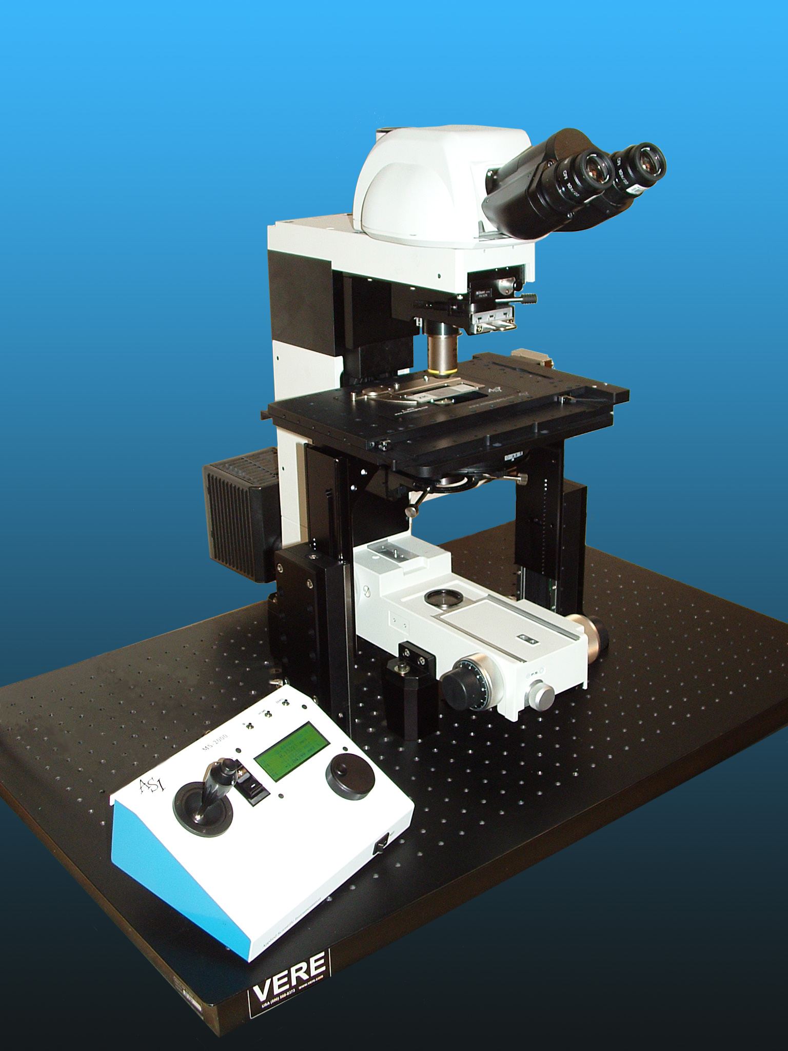
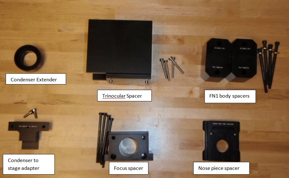
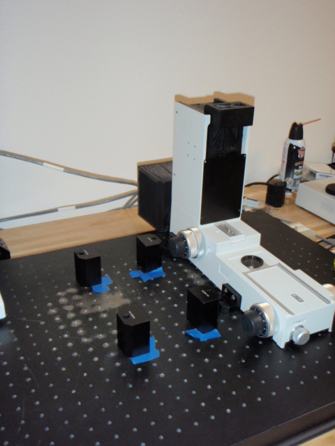
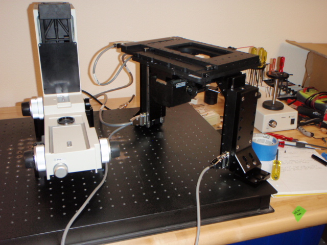
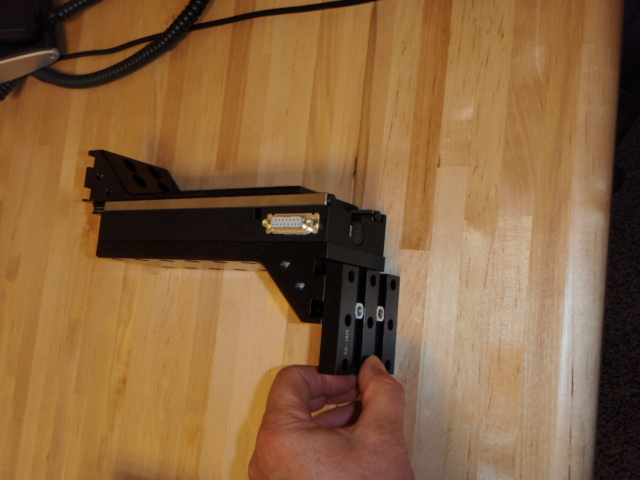
The FTP-2100 allows for 100 mm of Z travel when used with the adapter kit shown in figure 1 below. The dual LS-100 units move the complete XY stage in the Z axis and the spacers place the microscope body, trinocular head, focus bar, and objective nose piece in the correct location to allow the full range of travel. The travel range allows for a large number of samples to be used from standard glass slides to whole samples up to 100 mm in thickness. Assembly requires that the microscope & FTP-2100 be mounted onto an optical bread board. The spacers are designed to work with both standard & metric bread boards.
Step 1. Mounting the microscope
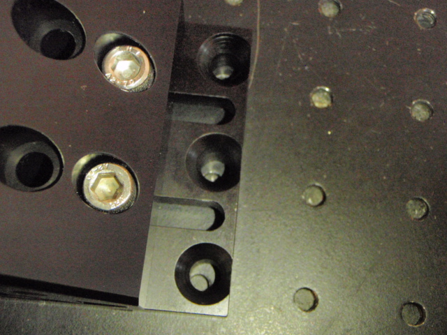
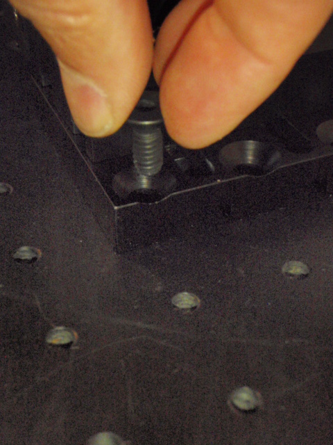
As shown in figures 2 & 3 above attached the standard Nikon adapter plates to the microscope body; please refer to the Nikon FN1 manual if necessary. Mark the foot print of these plates onto the bread board where you would like the microscope placed. As shown in figures 4 & 5 secure the microscope to the bread board with the supplied screws & washers. Standard bread boards use ¼-20 x 31/2 inch socket head cap screws to secure the 62 mm spacers supplied with the FTP-2100 / LS-100 systems.
Step 2. Installing the Focus & Trinocular Spacers
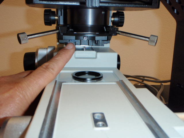
Before installing the focus & trinocular spacers please remove the trinocular head, objectives, & nose piece. Please refer to the Nikon FN1 manual for detailed instructions. Figure 6 & 7 show the location of the screws for these components.
AS shown in figures 8 & 9, Install the trinocular spacer, note alignment pins. Then use the 4 mm Allen wrench to tighten the 4 each 5 x 40 mm cap screws that secure the trinocular adapter to the microscope body.
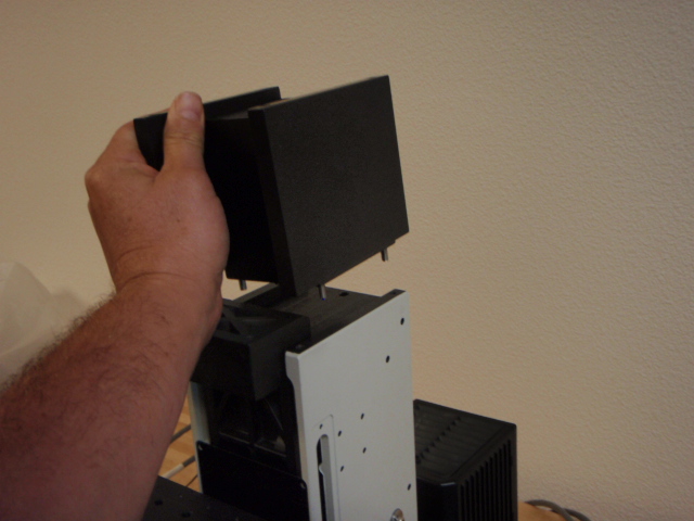
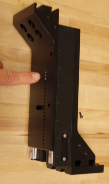
As shown in the above four photos of figure 10. Locate the focus spacer and position it onto the focusing block so that the machined lip on the spacer aligns with the back of the focus block. Use the 4 each 5 x 95 mm cap screws to secure the objective carrier to the focus block & tighten the screws with the 4 mm Allen wrench.
As shown in figure 11, install the trinocular mount back onto the microscope body, and secure it with the four original screws & 4 mm Allen wrench.

Step 3. Installation of Nikon FN1 condenser onto ASI Focus Translation Platform (FTP)
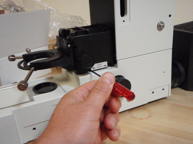
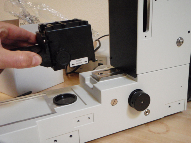
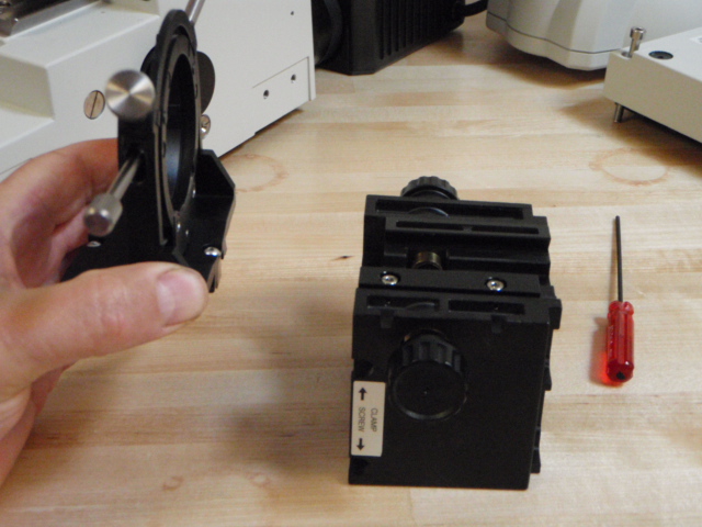
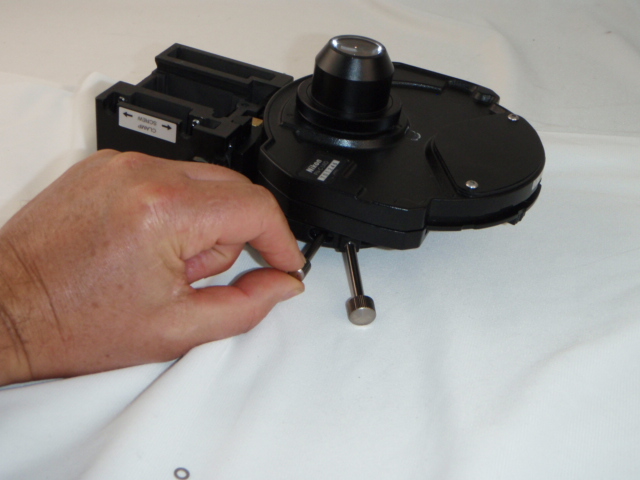
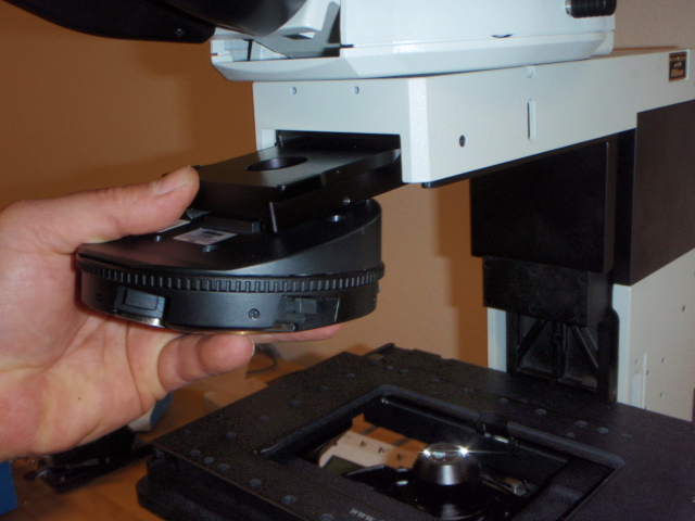
Remove the condenser assembly from the microscope as outlined in the FN1 manual. Use the 2 mm Allen wrench to loosen the two set screws & remove the condenser carrier as shown above.
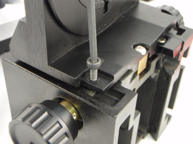
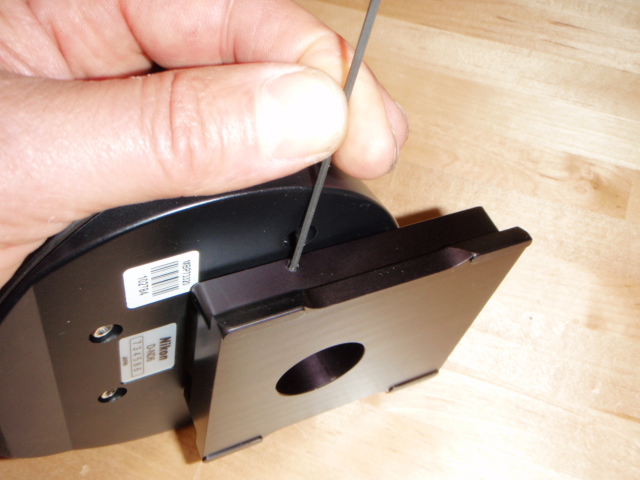
Use the 2 mm Allen wrench to remove the stop screw on the condenser carrier, and then completely remove carrier from the rack as shown. Turn the carrier around 180 degrees and then reinstall it onto the rack as shown. After installing the carrier completely onto the rack install the longer 8 mm stop screw as shown.
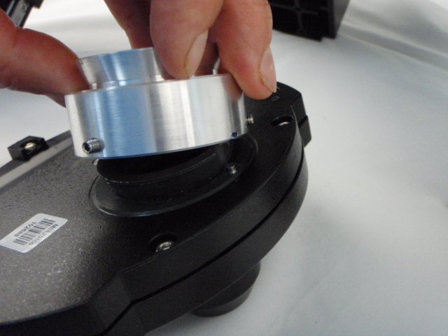
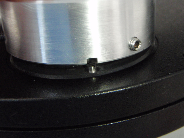
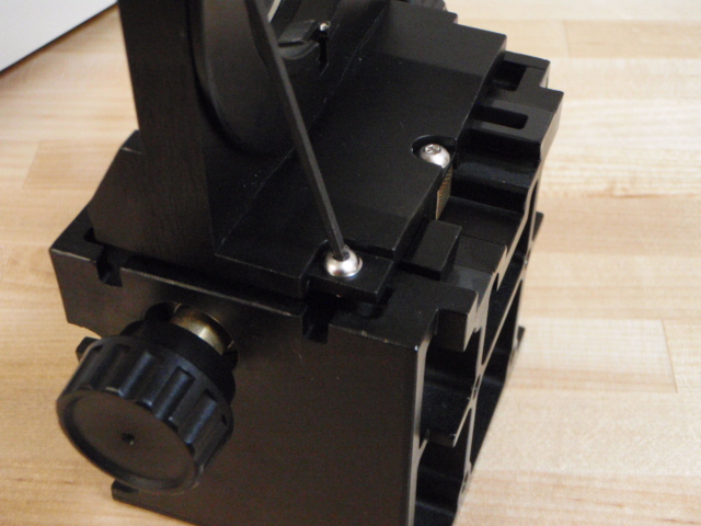
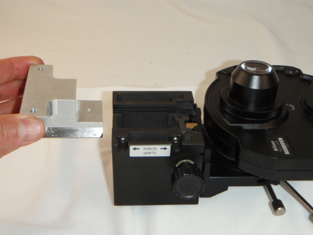
Install condenser extender onto condenser as shown; please note alignment pin & notch. Use the 2 mm wrench to secure the three set screws
Install the condenser onto the condenser carrier as shown & secure in place by tightening the thumb screw that holds the condenser in place
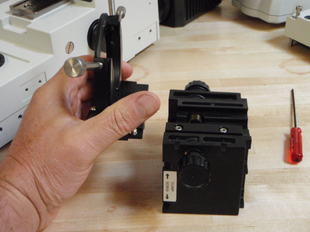
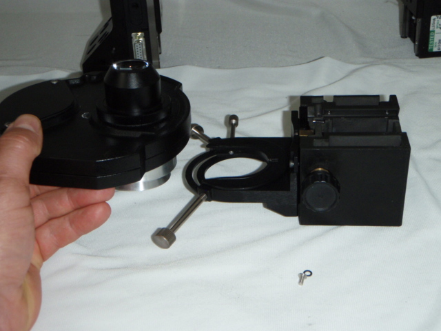
Use the 3 mm wrench to remove the two screws that secure the condenser carrier dovetail to the microscope as shown & remove the dovetail from the microscope body.
Install the condenser carrier dovetail to the ASI carrier adapter plate as shown. Please note alignment pin. Use the 3 mm wrench to tighten the two screws to secure the condenser carrier dovetail to the ASI carrier adapter plate.
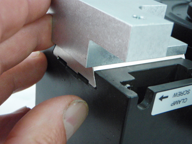
Slide the dovetail/adapter plate assembly onto the condenser carrier assembly as shown. Note that the end of the dovetail should be flush with the end of the condenser carrier assembly. Use the 2mm wrench to tighten the two set screws to secure the unit in place.
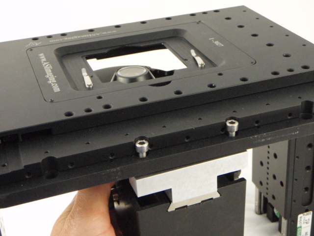
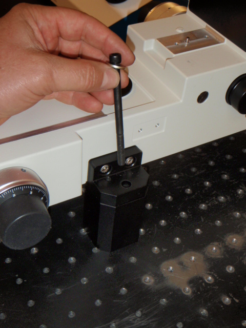
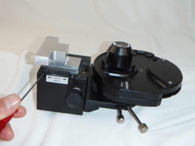
Locate the two 5 x 155 mm screws and install them through the holes in the back of the stage as shown. Align the carrier assembly with the screws and use the 5 mm wrench to secure the assembly onto the stage. Please make certain that these screws are tight.
Step 4. Installing Stage assembly
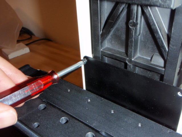
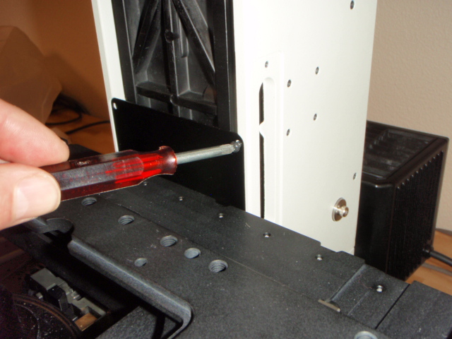
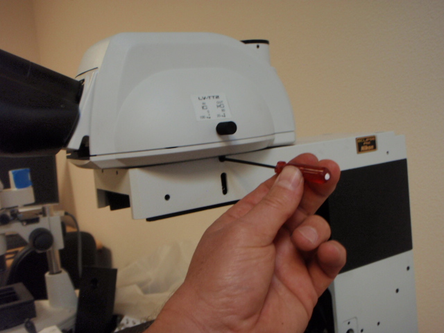
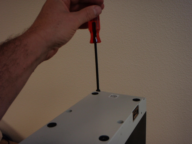
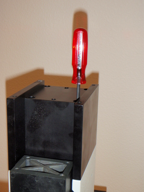
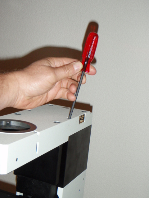
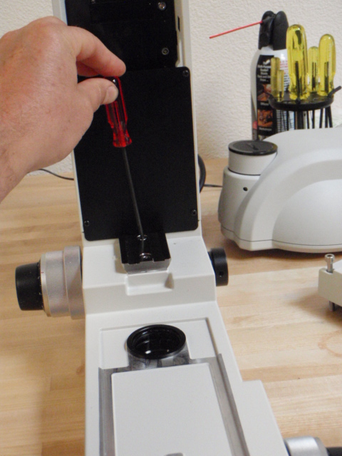
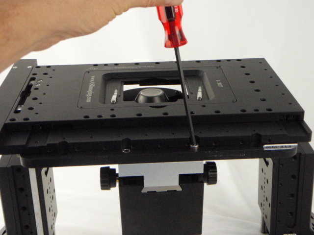
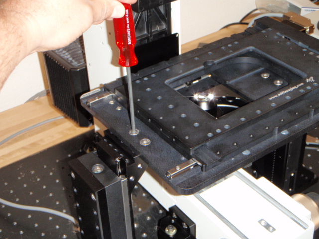
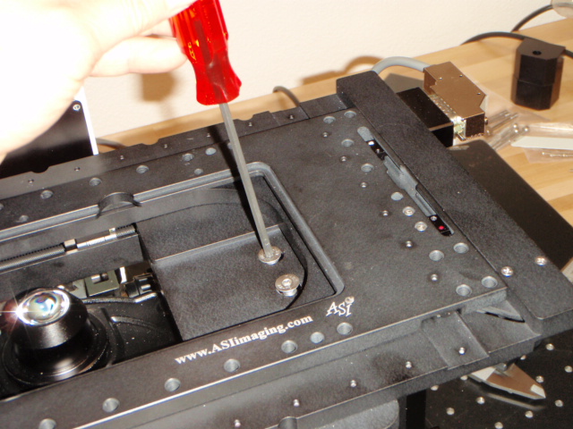
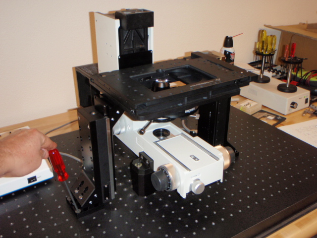
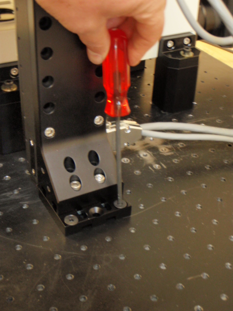
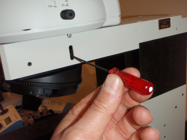
As shown in the above photos use a cross blade screwdriver to remove the two top screws from the microscope cover plate shown.
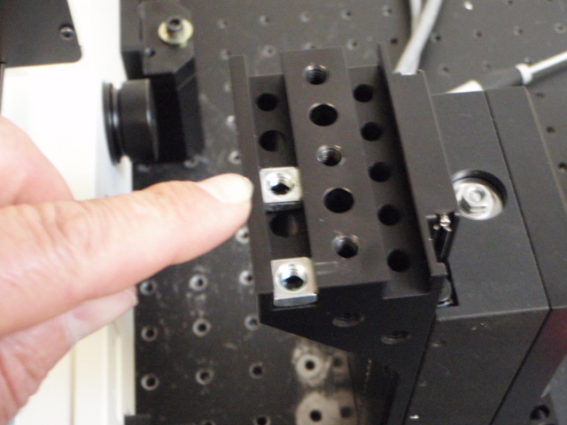
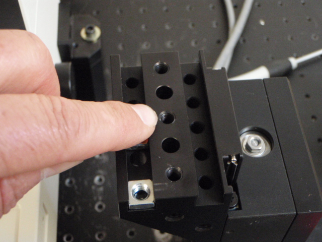
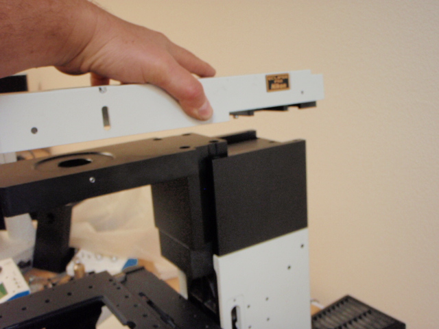
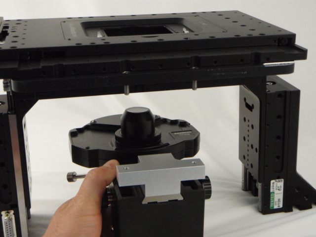
As shown in the photos above the XY stage mounts onto the top of the two LS-100 units via clearance holes located on the left & right hand sides of the stage bottom plate. The top & middle plates of the stage must be moved to the right to access these holes. Use the controller to move the stage, as it could be damaged if moved manually. Please note that the screws can mate with a number of points on the LS-100 units. But the outer nut assembly offers more clearance if needed. Please Also Note: The two screws that are on the left hand side are slightly longer than those used on the right hand side. 16 mm long screws on the left hand side & 14 mm long screws on the right hand side.
After installing the stage onto the two LS-1000 units connect the cables to the LS-100 units & stage as shown.
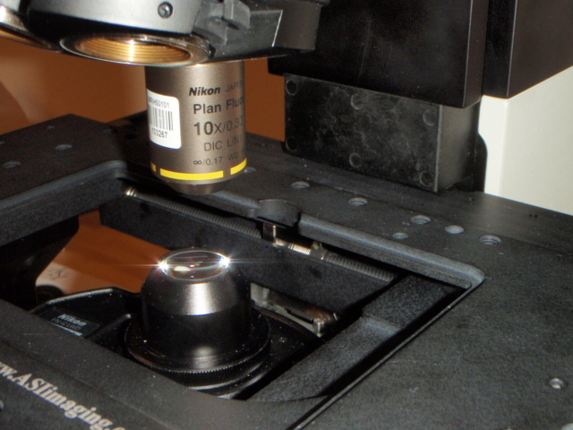

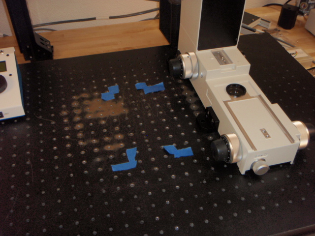
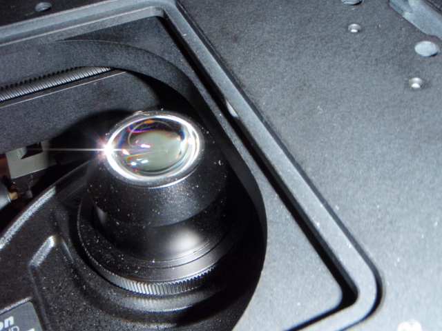
After installing the stage onto the two LS-100 units position the complete assembly so that the back of the stage bottom plate is aligned along the back of the microscope body; this will put the stage in alignment with the microscope. Move the complete assembly left to right to align the transmitted light path i.e. the center of the condenser extender should be centered over the lens on the bottom of the microscope that the transmitted light emits from. At full extension the top of the stage should just fit under the bottom of the focus bar as shown the upper right photo.
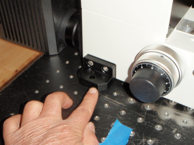
After the stage is properly aligned the bases of the LS-100 units should be bolted down the bread board & the LS-100 bottom brackets securely tightened. As shown in the above photos the adjustable bracket on the bottom of the LS-100 units can be moved along the Y axis after loosening the two silver screws. The bottom base can then be moved to align with screw holes in the bread board.
Step 5. Adjusting the limit switches
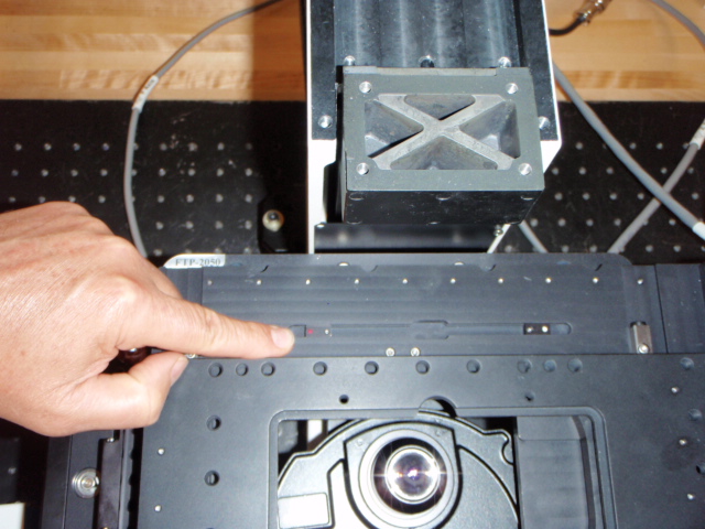
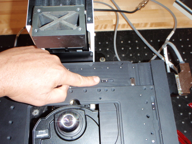
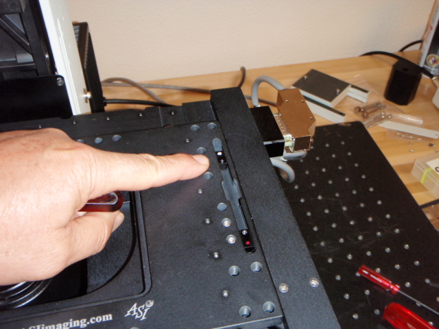
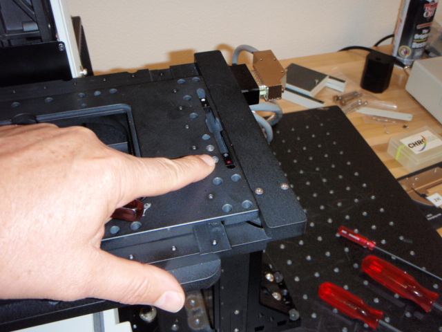
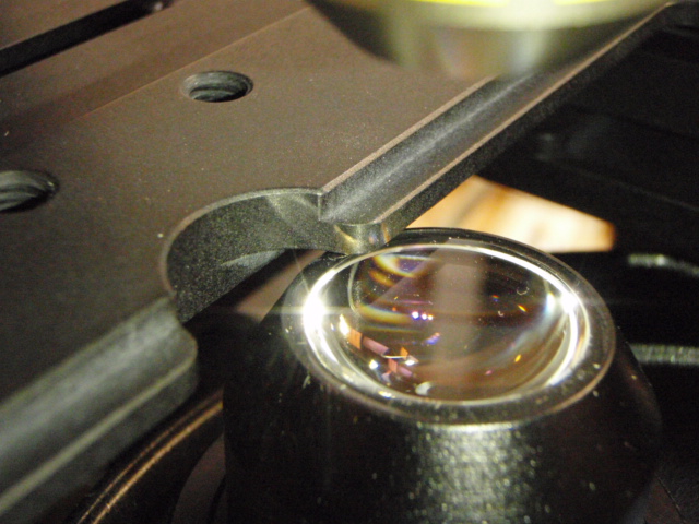
After the stage has been properly aligned and mounted onto the bread board please refer to the ASI manual’s section on adjusting the limit switches. The location of the XY limit switches are shown in the above photos. The limits on the LS-100 are accessed through the holes shown in the photo above on the right hand side. These limits need to be set to prevent the stage from running into the microscope base and to also prevent the stage plates from running into the condenser lens as shown in the photos below.
Step 6. Installing the rotary nosepiece spacer
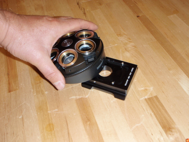
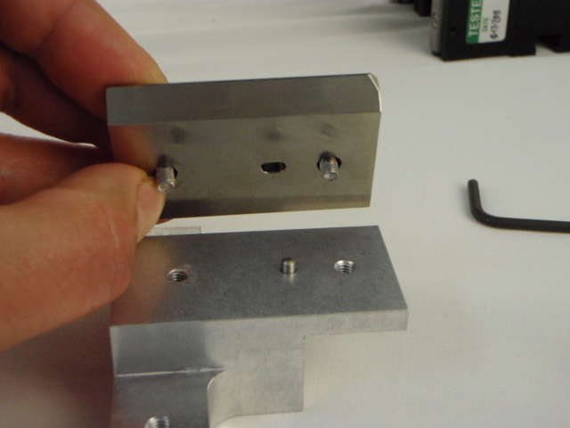
If you have ordered a rotary nosepiece spacer the unit is installed as shown in the above photos. The unit slides into the dovetail as shown & is pushed against the two screws that serve as stops; the setscrew is then tightened as shown to secure the nosepiece onto the spacer.
The nosepiece is installed into the focus carrier as shown; it needs to be mounted backwards to allow for the objectives to clear the back of the microscope body. The unit is secured in place by tightening the set screw shown.