Table of Contents
Synchronous Encoder Reporting
TTL Report Module
This section of the manual applies to the TTL_REPORT_INT firmware module. Including this module in the firmware allows for precisely synchronized encoder position reporting. The user's hardware supplies a TTL trigger to the MS-2000 that causes a processor interrupt which performs an encoder-read operation on all of the controller’s motorized axes. Any firmware build that includes this module is not capable of any other TTL input modes and will only perform the functionality of the TTL_REPORT_INT module.
Note: To enable TTL reports, set the TTL input mode to a non-zero value with the TTL X=# command. The input mode is ignored and only used to enable interrupts on the TTL input BNC, so just use TTL X=1.
If want reports on TTL output pulses, please see the TTL_OUT_REPORT firmware module instead.
Required Firmware Modules
Send the serial command BUILD X to check what firmware modules the MS-2000 controller has.
TTL_REPORT_INTSERIAL OUT(optional)BINARY_OUTPUT(optional)
Required Hardware Setup
To use the optional SERIAL OUT module, the controller requires the RS-232 SERIAL OUT port on the back of the MS-2000, this feature uses the second serial port to output the report.
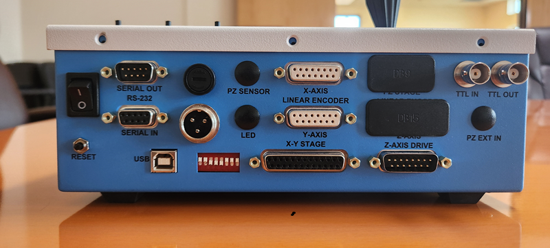
As you can see in the image, this MS-2000 has the serial port connector. You may have a controller configured for CRISP that replaces this port with a male DB9 connector. In that case, you will need to contact ASI to get a cable to split the connection between CRISP and the serial port.
You will also need a straight through serial cable (not a null modem cable) with a gender changer to connect the SERIAL OUT to the input of the serial port on another computer.
Timing Specifications

| Item | Symbol | Spec. Values | Unit | |
|---|---|---|---|---|
| Min | Max | |||
| Initial Read Delay | td | 3.0 | 10.0 | μs |
| Successive Axis Read Delay | ta | 11 | 13 | μs |
| Serial Transmit Delay | ts | 110 | 500 | μs |
| Transmit Time† | tt | 1.2 | 1.75 | ms |
| External re-trigger time† | text | 1.7 | ms | |
(†) 115200 baud, three axes
The encoder read operations follows the external trigger input as indicated in the timing diagram. The largest jitter component comes from the delay in executing the interrupt service routine that performs the read operations. Most of the time the interrupt proceeds with the minimum delay time specified. Occasionally, the reads are delayed until current data bus operations complete.
Data Transmission
There are two output modes, standard ASCII and binary. The binary output format requires the BINARY_OUTPUT firmware module and is always enabled if present.
The encoder position data is transmitted using the auxiliary serial port on the MS-2000 controller. The data baud rate for this port is set to be identical to the main serial communications port and is selected with DIP Switches 4 and 5. The Serial Out port on the MS-2000 controller should be configured with a straight-through female-to female RS-232 cable to communicate with a computer.
Binary data is sent in the following form (here illustrated for a three-axis system):
| AID | LSB | MB | MSB | HB | AID | LSB | MB | MSB | HB | AID | LSB | MB | MSB | HB | CR |
The axis identifier AID is the Low Level Format axis identifier string. The next four bytes represent the 32-bit encoder position value for the axis. This is a signed long integer value, low-byte first, high-byte last. This pattern is repeated for all of the axes that are present in the controller. A final terminating <CR> character (Hex 0x0D) completes the data stream.
The usual axis identifiers are as follows:
| Axis | Decimal Value | Hex Value |
|---|---|---|
X | 24 | 0x18 |
Y | 25 | 0x19 |
Z | 26 | 0x1A |
F | 27 | 0x1B |
Other output configurations are possible. Data can be sent to the usual Serial IN port, and/or the data can be sent in ASCII form. Contact ASI for details.
Error Conditions
An error condition will exist if the TTL triggers occur more quickly than the data can be sent out the serial port. When this condition is detected the error “87” (TTL_REPORT_BUFFER_OVERRUN) is appended to the internal error log buffer. If TTL triggers are present as the controller is powering up, some of these errors are to be expected.
With Piezos
Piezos do not have encoders to read. Prior to June 2024 firmware will report the target piezo position. Starting June 2024 the firmware reads the piezo's sensor voltage, however note that this is intrinsically a noisy signal which is closely related to the position but not as accurate as an actual encoder. This is being actively worked on by ASI; please contact us for details.
Note: In the distant past (probably before 2013) it was required to set the TTL mode to 6 to use the TTL_REPORT_INT module, but more recently any firmware build that includes the TTL_REPORT_INT firmware module is not capable of any other TTL input modes and will only perform the functionality of the TTL_REPORT_INT module.