Table of Contents
Leitz DMRB Microscope Motor Drive Installation
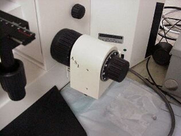
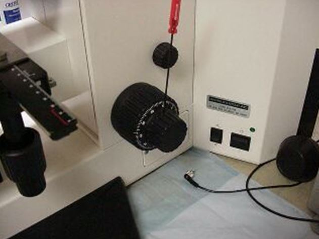
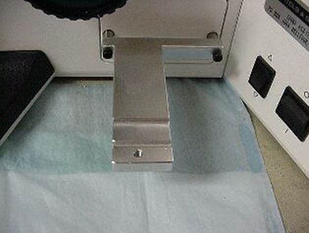
This procedure steps you through the installation and alignment of the ASI Z-axis motor drive onto the Leitz DMRB microscope. The ASI drive is attached to the right hand side of the microscope as shown in figure # 1. The drive is securely attached to the fine focus shaft of the microscope via a “metal on metal clamp”, as shown in figure # 5, which insures a solid and reliable connection. The drive is attached to the microscope’s body via two metal standoffs as shown in figures 3 & 4. The installation of the ASI drive does restrict the access to the transmittent / incident light selector switch, and filter switches. However, these switches can still be reached after the drive is installed. Precise alignment of the ASI drive onto the fine focus shaft of the microscope is accomplished through a dual axis sliding adjustment bar. Installing the ASI drive assembly involves five steps:
- Preparing the Drive for installation
- Removing the fine focus knob.
- Installing the metal standoffs
- Installing the ASI drive
- Aligning the ASI drive
- Installing the cover & the fine focus knob
The following tools are required for this procedure:
- small Phillips screwdriver
- 1.5 mm hex wrench (provided)
- 2.5 mm hex wrench (provided)
- 3 mm hex wrench (provided)
- 1/16” hex wrench (provided)
- 7/64” hex wrench (provided)
Note: the terms left and right refer to the sides of the microscope as viewed from the front of the microscope and assemblies.
Step 1 - Preparing the Drive for Installation
Locate the ASI drive assembly and use the 3 mm hex wrench to remove the horizontal adjustment screw, and remove the drive from the side plate assembly. The side plate assembly is shown installed on the microscope in figure # 3.
Step 2 - Removing the right fine focus knob
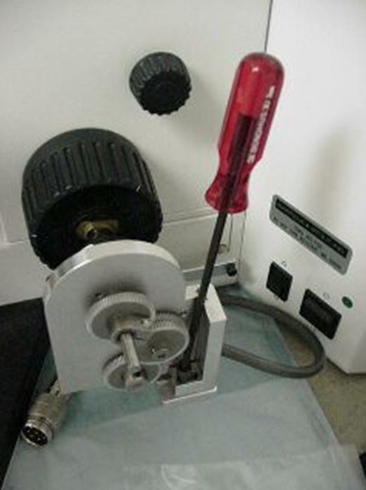
Remove the fine focus knob from the microscope as shown in figure # 2
Use the 1.5 mm Allen wrench to loosen the set screw that is located on the fine focus knob, remove the knob by pulling it off
Step 2 – Installing the metal standoffs
Use the small philips/cross bladed screw driver to remove the rear 3x5mm screws that secure the filter button cover to the microscope. After removing the screws install the longer 3x25mm through side plate assembly and the metal standoffs and attach the side plate to the microscope as shown in figure #3. Use the 2.5mm allen wrench to securely tighten the 3x25mm screws thus securing the side plate to the microscope.
Step 3 – Installing and aligning the drive
a.) Locate the ASI drive & the 3mm & 7/64th Allen Wrenches. Use the7/64 hex wrench to loosen, but do not remove, the vertical adjustment screws located on the rear of the motor drive. (See figure # 4) When the vertical adjustment screws are loose the motor drive should move freely about in the vertical axis.
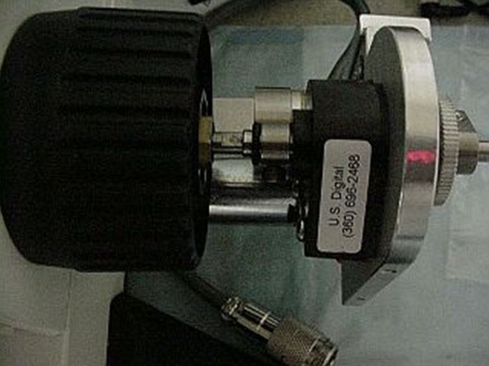
b.) Check to insure that the clamp on the hollow end of the drive shaft which protrudes from the black encoder on the inside of the motor assembly is loose. If it is not loose loosen it with the 7/64” allen wrench. The black o-ring will keep the clamp from falling off the shaft.

c.) Hold the motor assembly in your right hand, and push against the left fine focus knob with your left hand as to keep the fine focus shaft from moving. Position the hollow end of the drive shaft (protruding from the black encoder) over the fine focus shaft on the microscope as shown in figure # 5. Orient the motor assembly so that the two shafts are aligned, then push the motor assembly onto the microscope until the notch on the end of the vertical adjustment bar mates with the grove on the top of the side plate assembly.
d.) While continuing to hold the motor assembly in place use the 4mm the horizontal adjustment screw that was removed in step # 1 to secure the drive assembly to the side plate assembly as shown in figure #6. Do Not tighten the horizontal adjustment screw at this time.
e.) Use the7/64 Allen wrench to securely tighten the clamp on the end of the ASI drive shaft. Please Note: This clamp must be securely tightened or slippage may occur.
Step 4 -Aligning the drive
Carefully position the motor assembly along the, vertical & horizontal axis while rotating the left fine focus knob until minimum drag is felt. Please Note: The ASI drive is usually self aligning so little or no movement of the drive may be necessary. Use the 7/64 & 3mm allen wrenches tighten the vertical & horizontal adjustment screws, as shown in figures #4 & 6, at the position where minimum drag is felt. Recheck for minimum drag on the fine focus shaft by turning the right fine focus shaft. Repeat alignment procedure if necessary.
Step 5 - Installing the cover
Use the 1/16” Allen wrench to remove the three screws from the edges of the drive assembly. Locate the ASI cover plate. Place it in position over the motor drive assembly and secure it with the screws just removed. Place the right fine focus knob over the protruding end of the drive shaft and secure it in place with the original set screw using the 1.5 mm Allen wrench.