Table of Contents
Replacing LED boards in ASIs LED Illuminator(MIM-LED-LAMP)
This Technical note walks users thru on how to replace the LED board(or LED) in ASIs LEDs illuminator (MIM-LED-LAMP or MIM-LED-LAMP-NR assembly)
Tools Needed
- 1.5mm Hex key or allen wrench
- 2mm Hex key or allen wrench
- 2.5mm Hex Key or allen wrench
Step 1: Removing Illuminator from Microscope
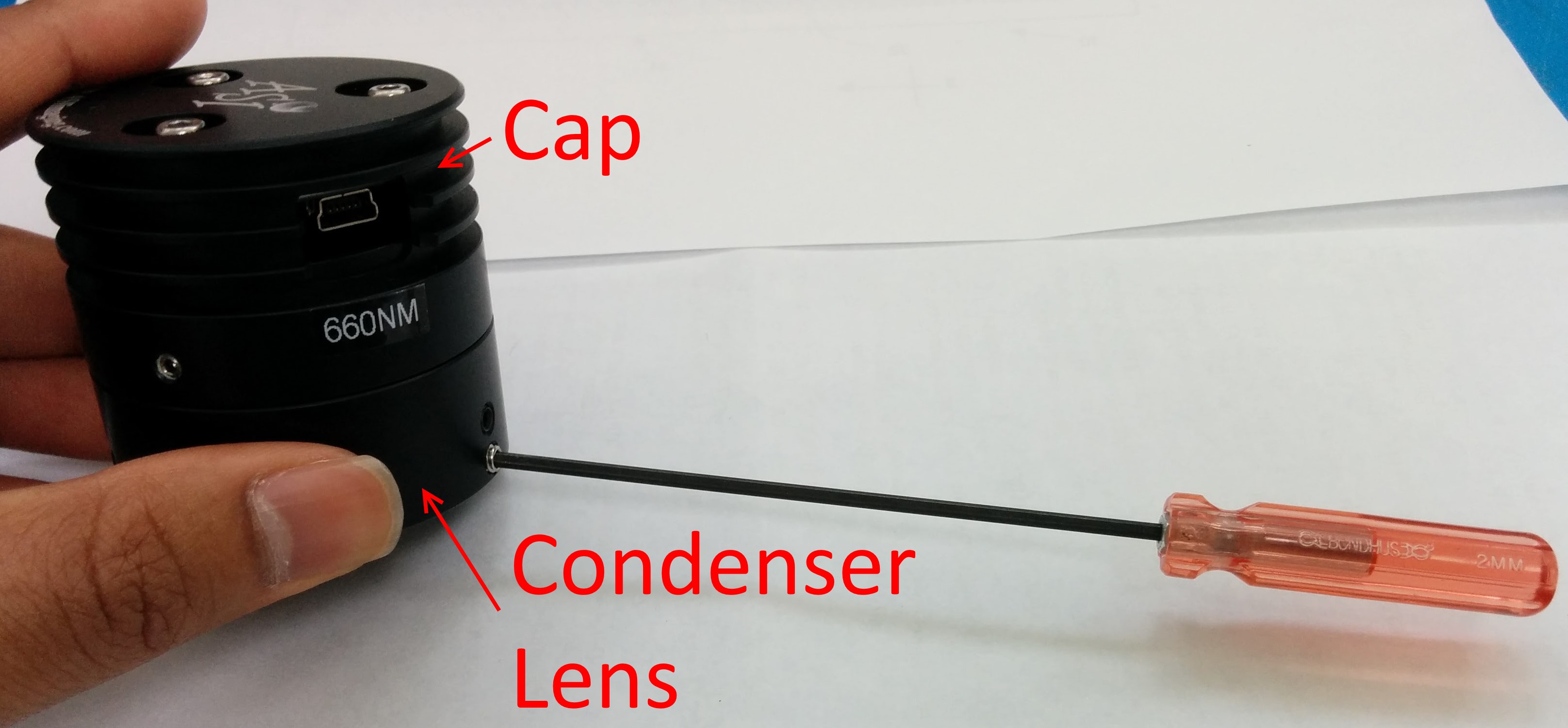
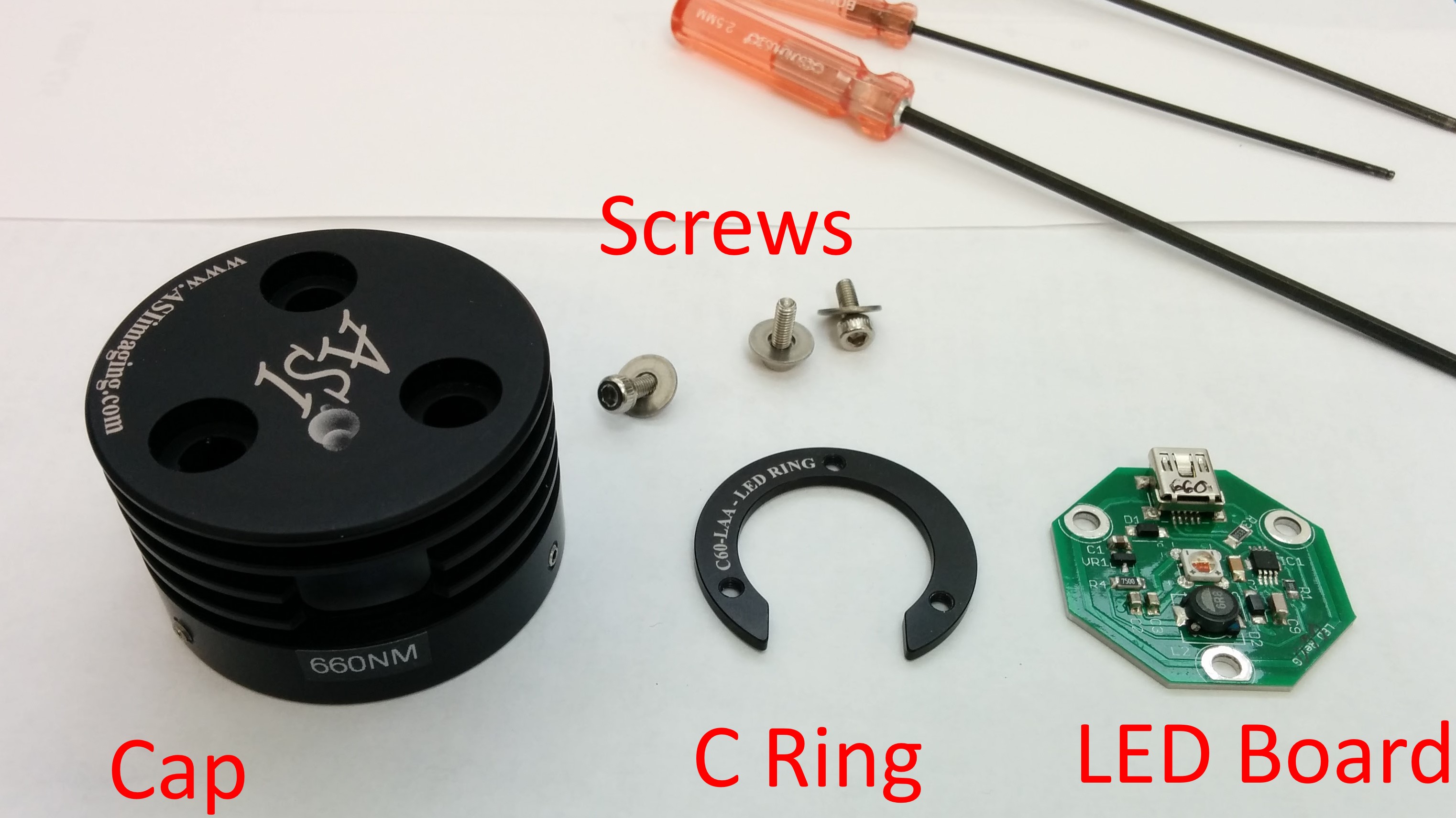
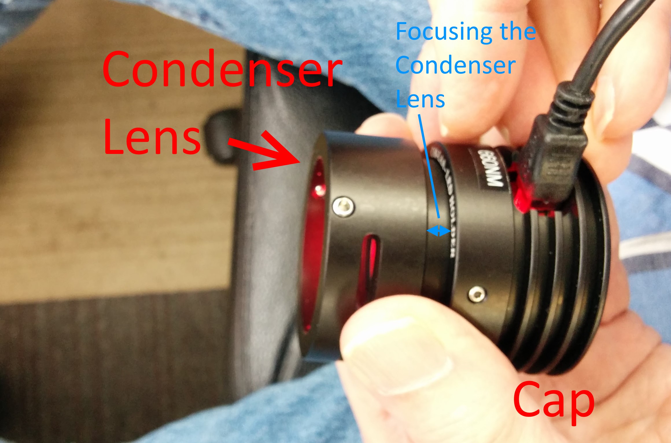
The MIM-LED-LAMP assembly consists of the Cap (which houses the LED board and acts like a heatsink) and the Condenser Lens.
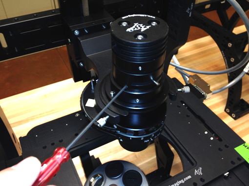
Separate the MIM-LED-LAMP assembly from rest of the microscope(or RAMM). The Condenser lens is held on the microscope with Three 2mm setscrews. Use a 2mm allen wrench to loosen the setscrews and detach it from the scope.
Step 2: Removing the Condenser lens
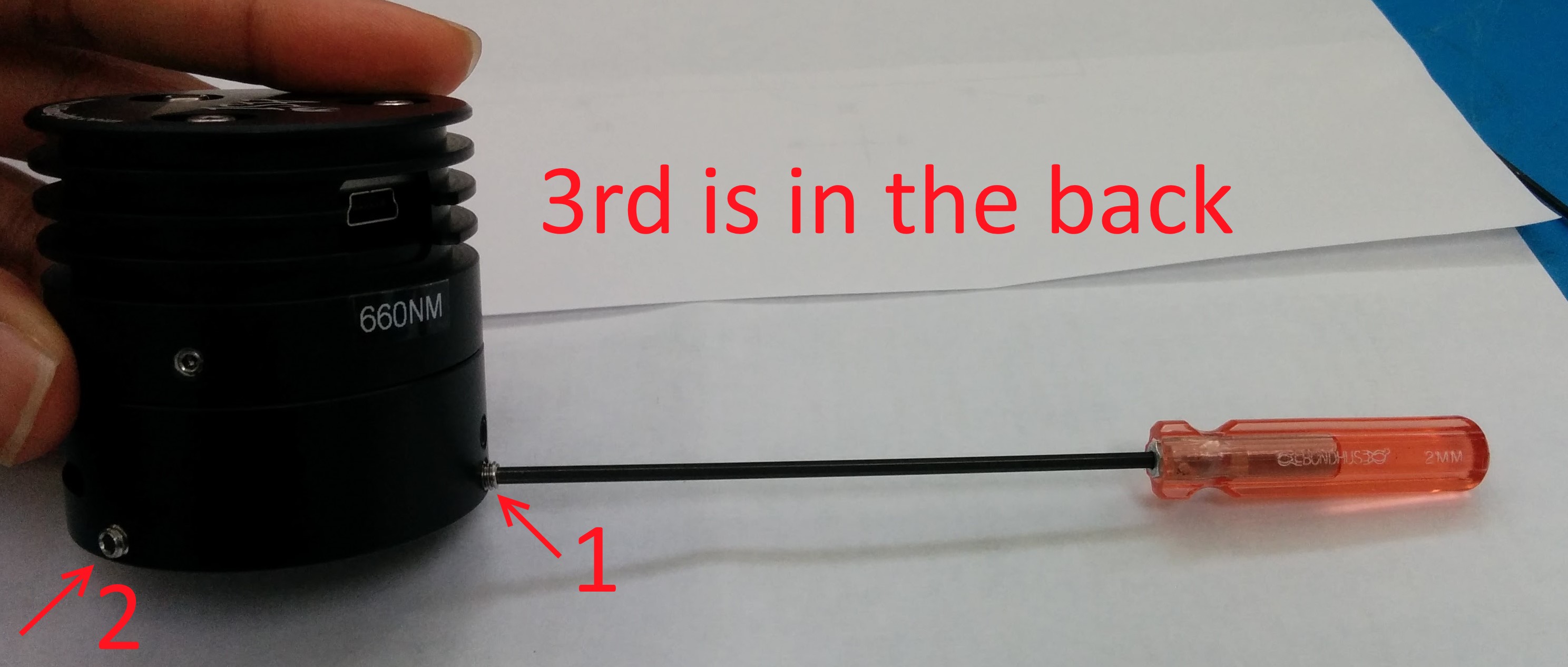
Now Separate the Cap from the Condenser lens. The Cap and the Condenser lens ring are held together with three 1.5mm set screws. User a 1.5mm allen wrench to unscrew them. Location is shown in pictures below.

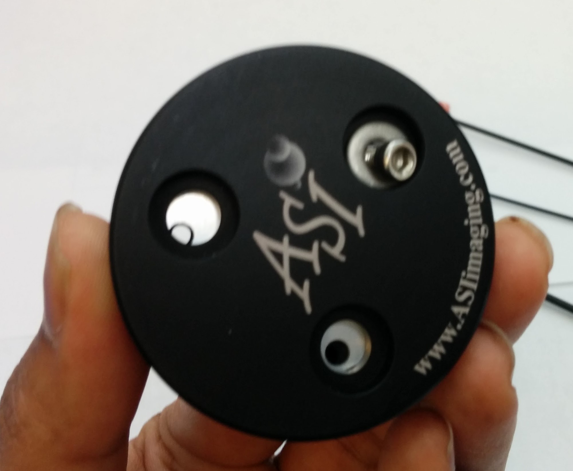
Step 3: Removing the LED board
We are down to the Cap.

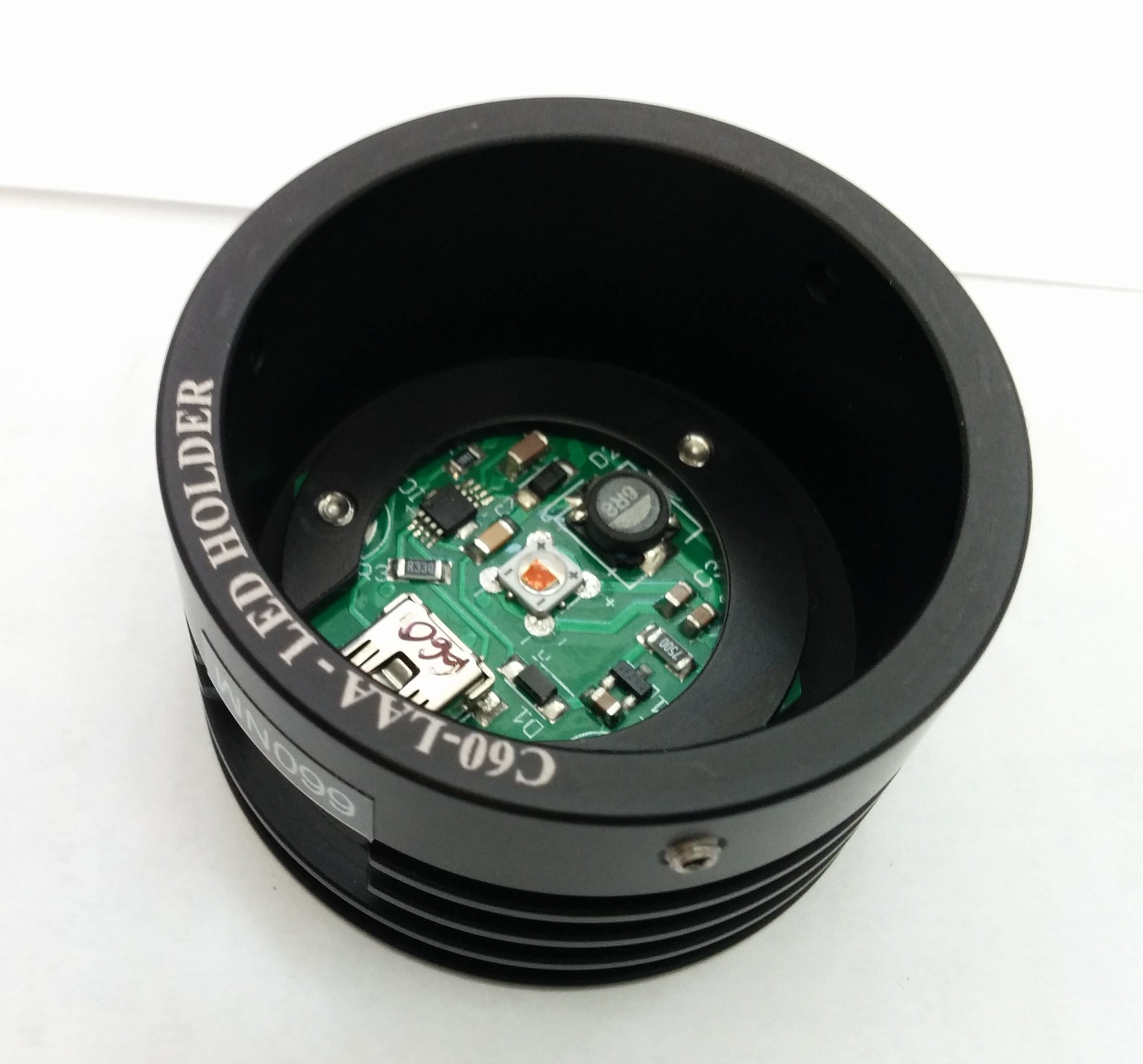
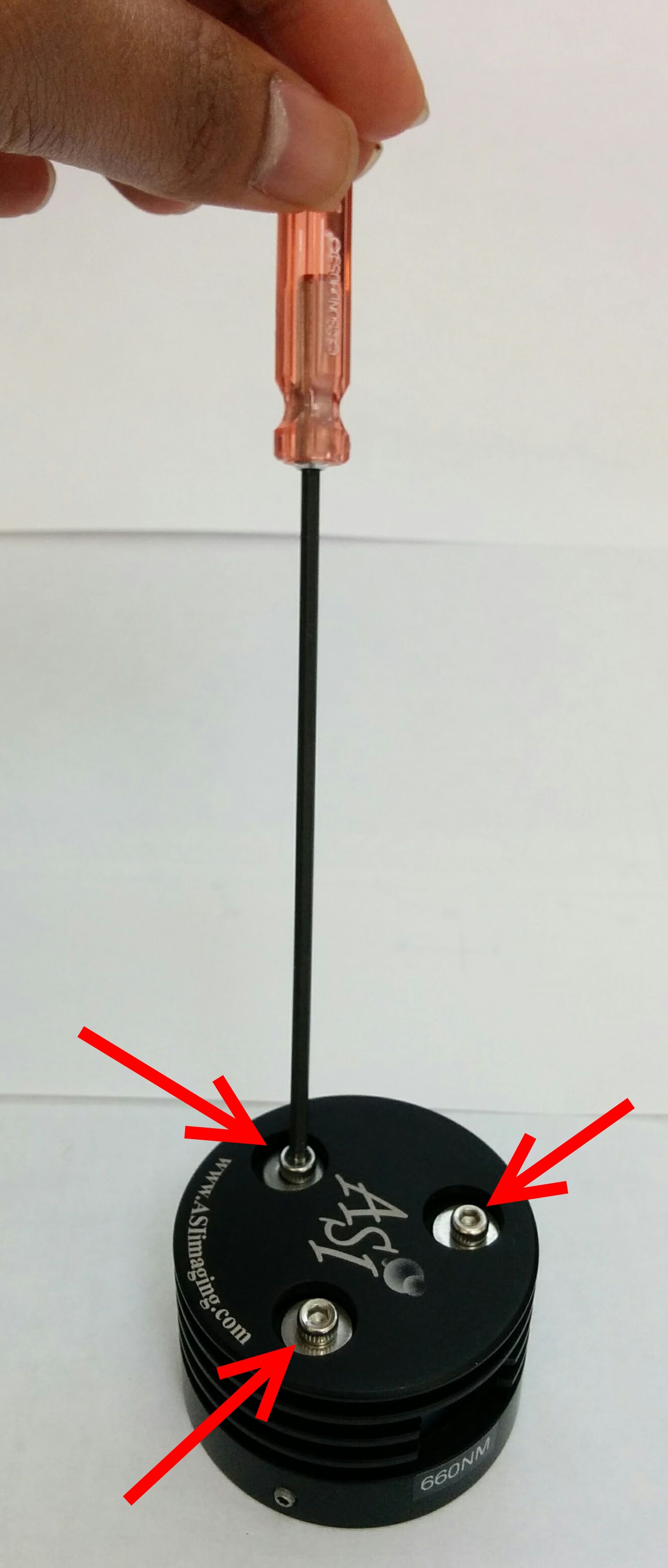
(Formerly, the LED board was held with a C ring and three M2.5 screws.)
Use a 2.5mm Allen wrench to screw the three M2.5 screws. This will separate the LED board from the cap.
Step 4 : Reassembly with new LED board
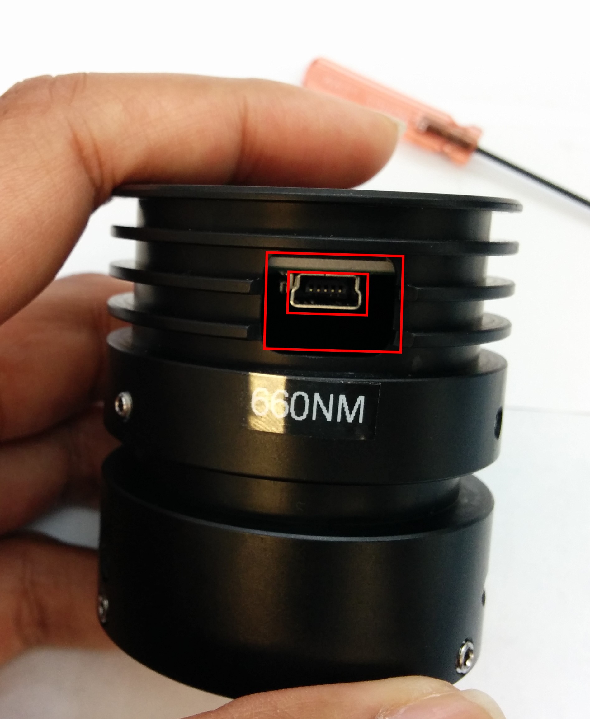
Now to reassemble the Illuminator with the new LED board. Drop it into the cap. Orient it such that the Connector is accessible thru the opening.
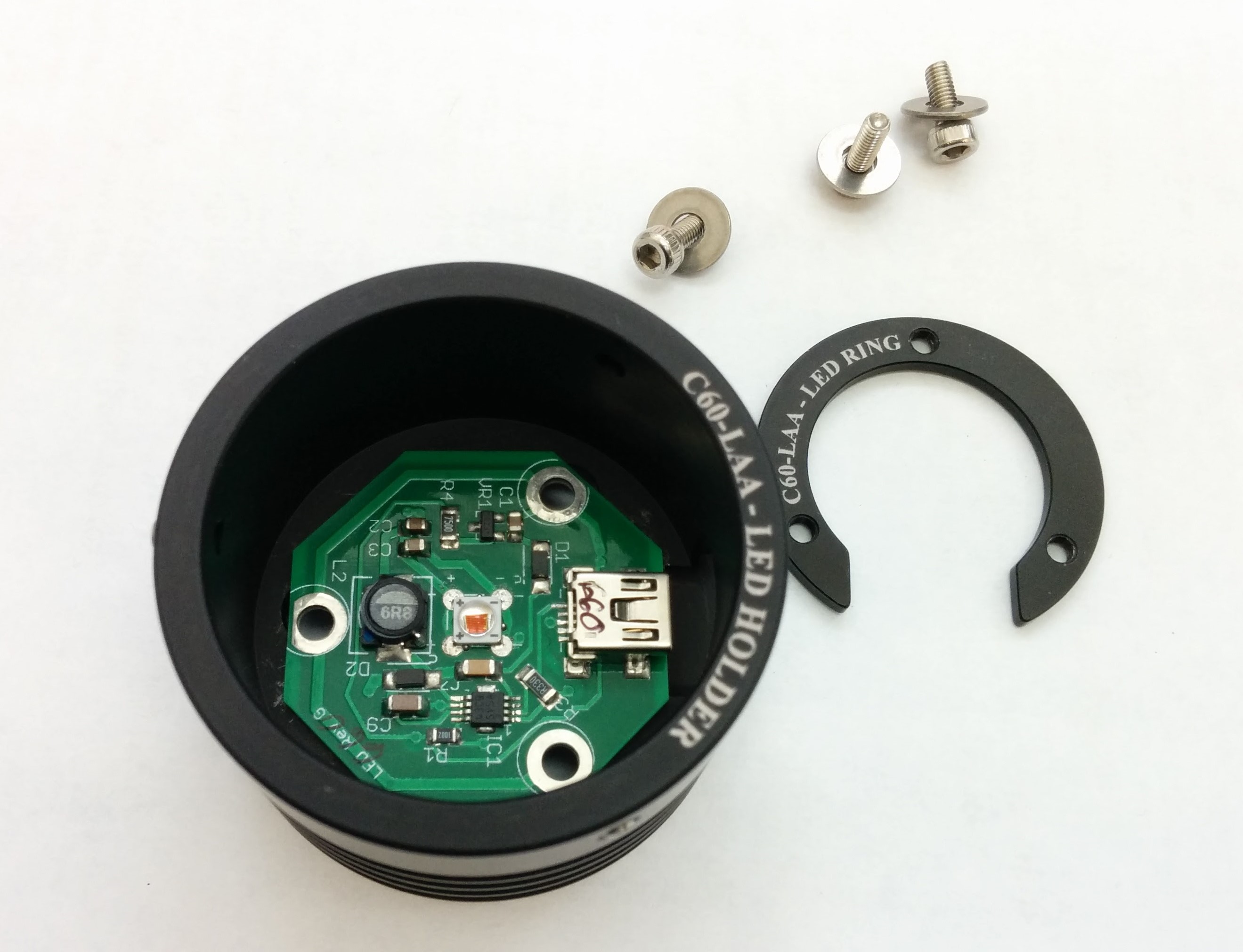
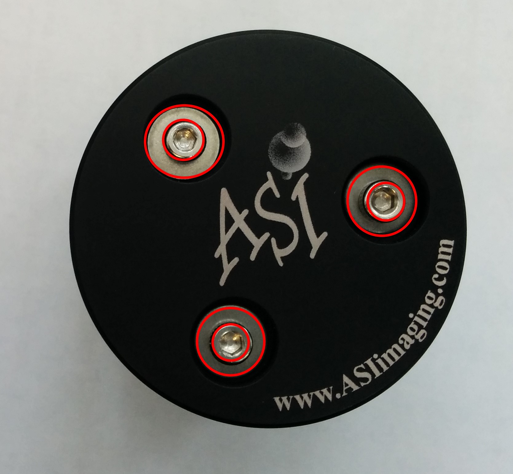
Flip the Cap so you can access the Mounting holes for the M2.5 screws.
Drop the three M2.5 screws one by one and screw it into the nut mounted on the LED board.
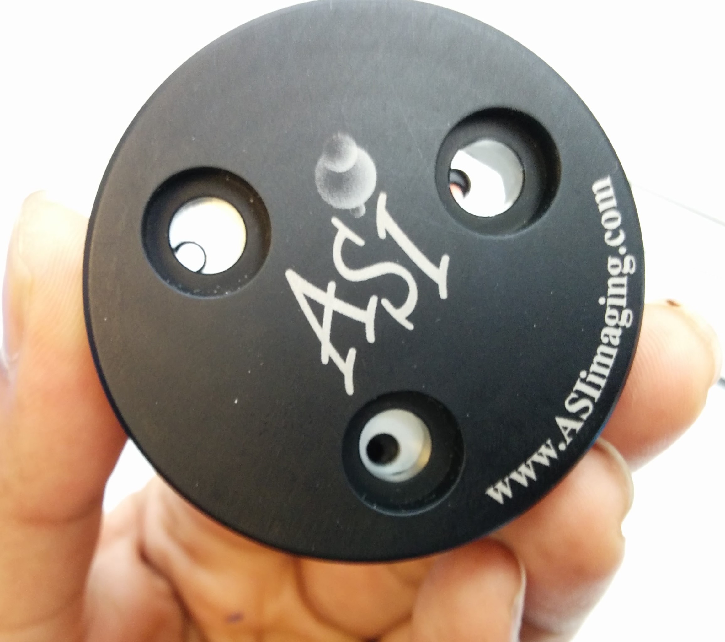
Step 5 : LED board XY alignment
User might notice that there is a lot of clearance on the M2.5 mounting holes. This is to give the user flexibility in adjusting the LED boards XY position to better align with the microscope optics.
For now , try to position the LED board as close to cap center, and the LED boards's connector is in middle of the connector's openinging.
The Three M2.5 screws are accessible even when the illuminator is fully assembled.User can go board loosen these screws and adjust the xy position of the LED board anytime.
Step 6:Attaching and Aligning the condenser lens
ReAttaching the condenser lens. The Lens needs to be at a certain distance from the LED board to focus the light correctly. The procedure is as follows.
- Put the Condenser lens into the Cap , do not tighten the set screws yet.
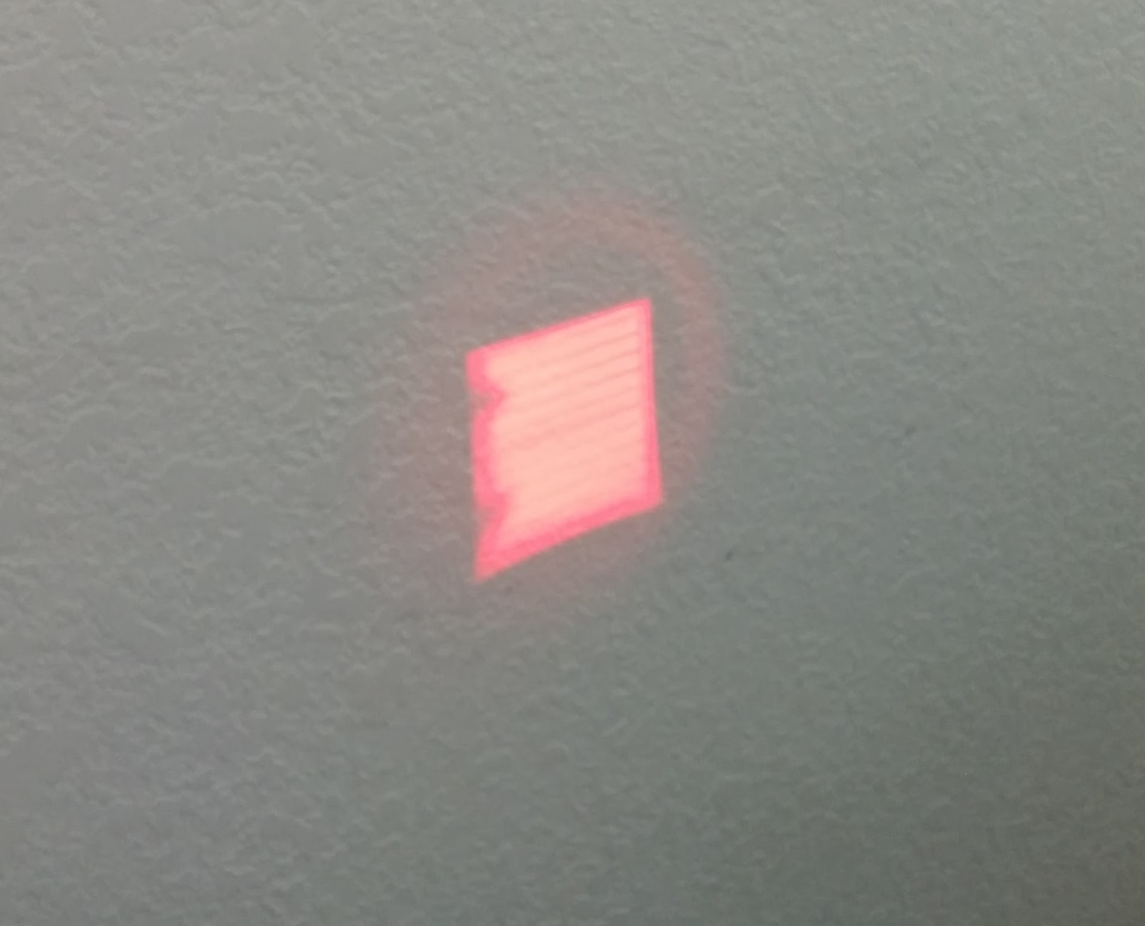
- Power the LED Illuminator , and shin the light onto a distant wall (about 6 feet away)
- Now Focus the condenser lens assembly in and out of the cap, until you see an image of the LED die.
- Lock this focus , by tightening the three 1.5mm setscrews.
Assembly is complete, reattach the Illuminator back onto the scope. Contact support[at]asiimging[dot]com for additional support if needed.