Table of Contents
LS-50 and other Linear Stages
This manual pertains to ASI’s LS-Series linear positioning stages used with the MS2000 or Tiger Multi-card controller systems.
This manual will describe the installation, operation, and programming for basic system components, plus sections for applicable options. Please contact ASI regarding addition options if you wish to upgrade your system.
Introduction


- Standard units come with built in rotary encoders
- Linear encoder units are also available for unsurpassed resolution & accuracy
- Precision ground cross roller bearings and guides are used to
The LS linear stage provides sub-micron accuracy, and derives precise control through the use of closed-loop DC servomotors employing high-resolution rotary encoders for positioning feedback. An optional linear encoder can also be added to the unit to provide even greater positioning accuracy. The stage utilizes crossed-roller slides, precision lead-screws, and zero-backlash miniature geared DC servomotors for smooth and accurate motion. The unit offers 50 mm of precise travel, and can be used either vertically or horizontally, and can carry loads up to 4.5 Kg (10 lbs).
The unit can be configured with a number of lead screw options as outlined in the table below. In our standard rotary encoder configuration, and using ASI's MS-2000 control electronics, resolutions in the 50-to-100 nm range can easily be obtained. Repeatability factors of less than 300 nm rms are also obtainable.
The optional linear encoder provides a resolution of 20 nm and can be used to provide the ultimate feed back device to increase these factors to a greater degree. Actual resolution & repeatability factors vary somewhat with the load so please contact ASI for these specifications.
The MS-2000 controller accepts industry standard commands, provides automatic backlash correction, and allows RS-232 or USB communication with a host computer.
| Lead Screw Pitch Options | Rotary Encoder Resolution | Maximum Speed (Dynamic range = 100) |
|---|---|---|
| 6.35 mm | 88 nm | 7 mm/sec |
| 1.57 mm | 22 nm | 1.75 mm/sec |
| 0.317 mm | 4.5 nm | 0.35 mm/sec |
WARNING: When installing the LS unit you must insure that the proper length 1/4-20 screws are used. If the screws are too long, i.e. exceed the thickness of the plate that they are being screwed into, they can press against the adjoining plate and cause serious damage to the unit .
Features and Capabilities of an L-Series with a Controller
- Closed-loop DC servo motor control of the X, Y, Z and Theta axes for precise positioning and highly repeatable focusing
- Sub-micron repeatability on all axes
- Wide dynamic speed range with adjustable trapezoidal move profiles
- Compact ergonomic tabletop control unit is 3½ x 9 x 6½ inches (9 x 23 x 16½ cm)
- Smooth adjustable dual-range joystick control
- Microprocessor control USB communications
- Upper and Lower Maximum Travel Hall-effect limit sensors
- Electronic torque limit on drives minimizes damage by runaway stage
- Other functions including programmable positioning patterns and scans
LS-Series Linear Stages
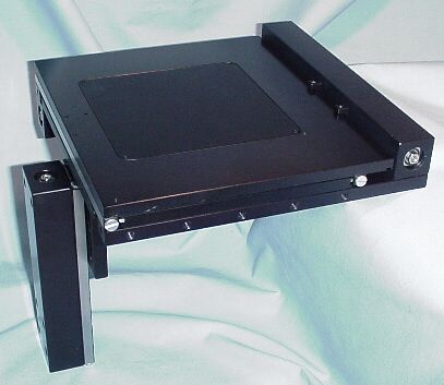
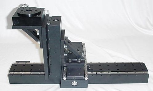
The LS-50 and LS-100 linear stages provide a simple building block approach to multi-axis motion control when used with ASI’s MS2000 or Tiger controller. Illustrated below are a few configuration possibilities for these stages, sometimes in combination with the ASI XY stage. The LS stages have multiple tapped ¼-20 holes on one inch spacing for mounting other stages and brackets. The stage slider has ¼-20 tapped holes as well as counter-bores for ¼ Allen head screws. XY combinations can be built most compactly at manufacture using counter-bores on the back side of the slider for attaching another LS unit perpendicular to the first.


The photos above show a pair of LS stages set up for XY motion, and an ASI stage mounted to an LS-50 Z-axis unit. The LS-50 could also be mounted directly below the ASI stage as shown below, where the LS-50 is extended to its maximum travel.

The LS-Series linear stages provide sub-micron accuracy, and derives precise control through the use of closed-loop DC servomotors employing high-resolution rotary encoders for positioning feedback. An optional linear encoder can also be added to the unit to provide even greater positioning accuracy. The stages utilize crossed-roller slides, precision lead-screws, and zero-backlash miniature geared DC servomotors for smooth and accurate motion. The units come in several travel ranges; 50mm, 100mm, and 300mm are available. They can be used either vertically or horizontally, and can carry vertical loads up to 4.5 Kg (10 lbs), limited by the rating of the lead-screw anti-backlash nut. Mounted horizontally, the loads can be larger. The unit can be configured with a number of lead screw options as outlined in the table below. In our standard rotary encoder configuration, and using ASI's MS-2000 control electronics, resolutions in the 50-to-100 nm range can easily be obtained. Repeatability factors of less than 300 nm RMS are also obtainable.
| Lead Screw Pitch Options | Rotary Encoder Resolution | Maximum Speed (Dynamic range = 100) |
|---|---|---|
| 6.35 mm | 88 nm | 7 mm/sec |
| 1.57 mm | 22 nm | 1.75 mm/sec |
| 0.317 mm | 4.5 nm | 0.35 mm/sec |
The optional linear encoder provides a resolution of 20 nm and can be used to provide the ultimate feed back device to improve the repeatability and absolute accuracy of the system. Actual resolution & repeatability factors vary somewhat with the load so please contact ASI for these specifications.
The MS-2000 controller accepts industry standard commands, provides automatic backlash correction, and allows RS-232 or USB communication with a host computer.
Adjustable Limit Switches
Newer Dovetail Style
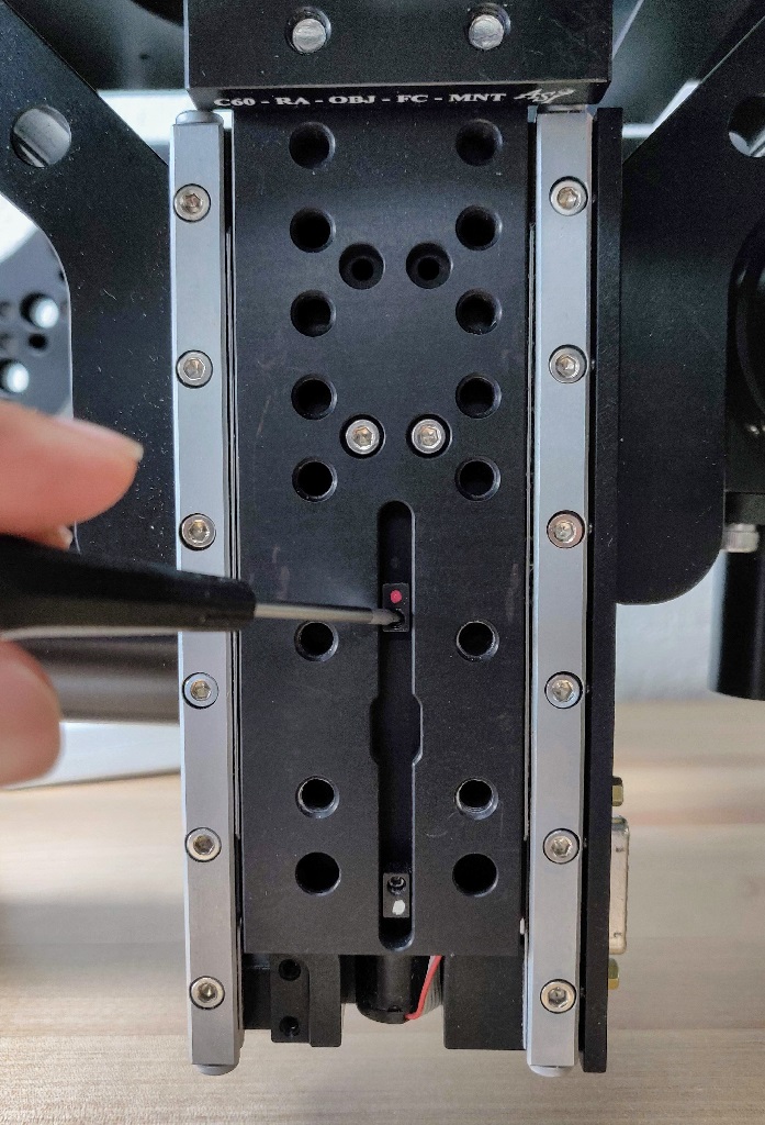
LS stages are equipped with adjustable magnetic limit switches that can be used to limit the stage travel range. The limit magnets are housed in a dovetail assembly in the face of the LS stage slide. The magnets polarity dependent and are marked with either a red or white paint dot. The magnet with the white dot is the Lower limit (stops travel directed away from the motor end of the stage), the red dot for the Upper limit. When the limit magnet is felt by the Hall sensor in the stage body, the limit indicator will show on the controller display and motion will stop in the direction into the limit. Use a 1.5mm allen (or hex) wrench to adjust the limit.
Old Style
On older linear stages, the limit magnets were held in a series of small holes, kept in place with a 0.05 in set-screw. Limits were adjusted my unscrewing the set-screw, extracting the magnet and placing it in a different hole. When doing this, keep the magnet stuck to the tip of the set screw so it doesn't flip over (north and south poles indicate the two different limits.
Installation Instructions
WARNING: When installing the LS stages you must insure that the proper length 1/4-20 screws are used. If the screws are too long, i.e. exceed the thickness of the slider plate, they can press against the adjoining plate and cause serious damage to the stage. The magnet with the white dot is for the Upper travel limit (travel away from the motor end of the stage), the red dot magnet for the Lower limit. Use a 1.5mm Allen key to loosen the lock set screw and move the magnet to the correct position. When the Hall sensor in the stage body senses the magnet, the limit indictor on the controller display will activate.
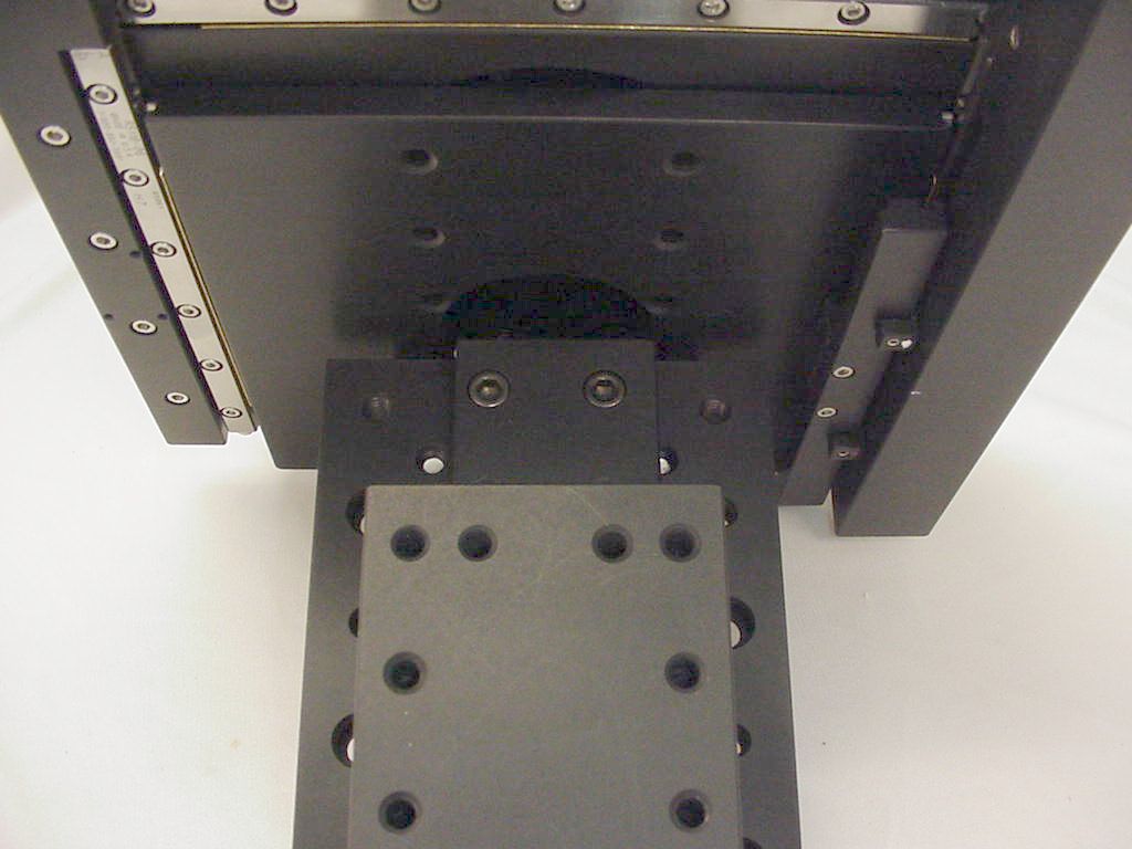
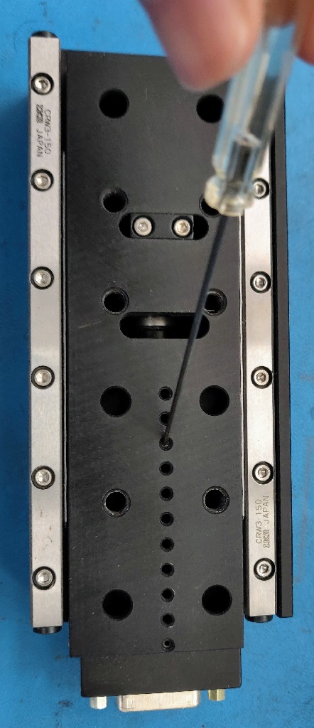
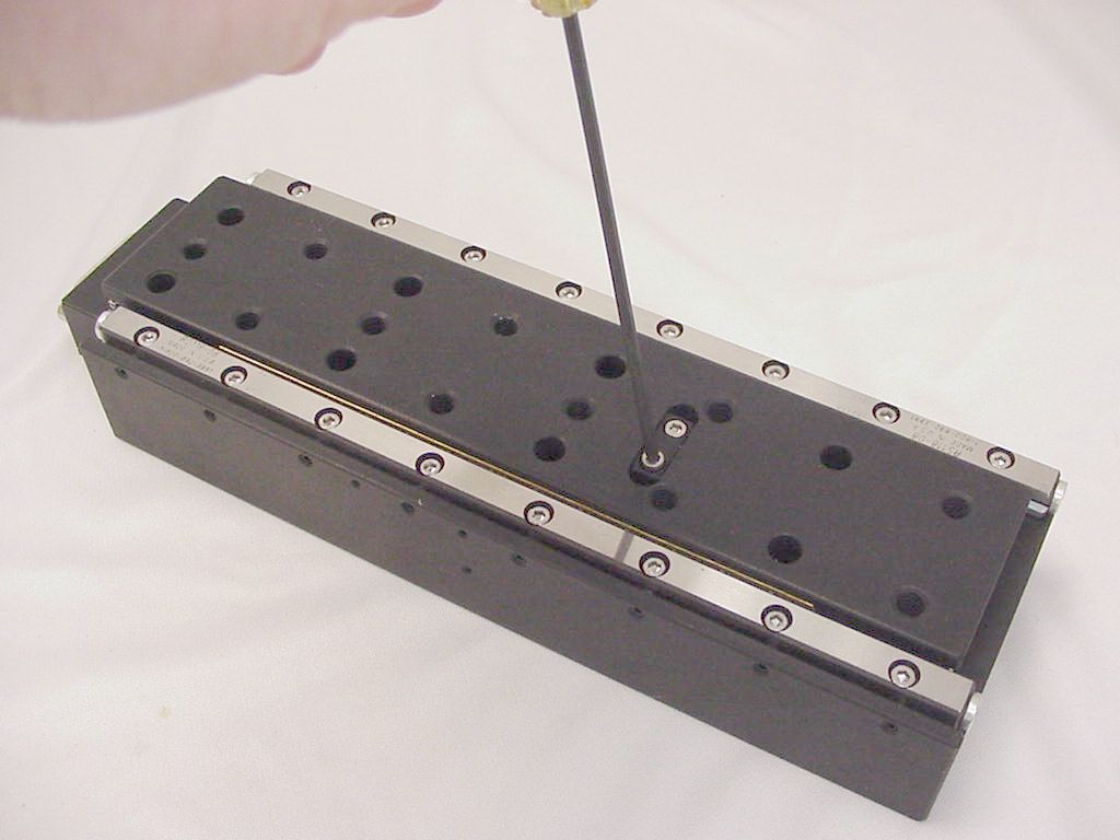
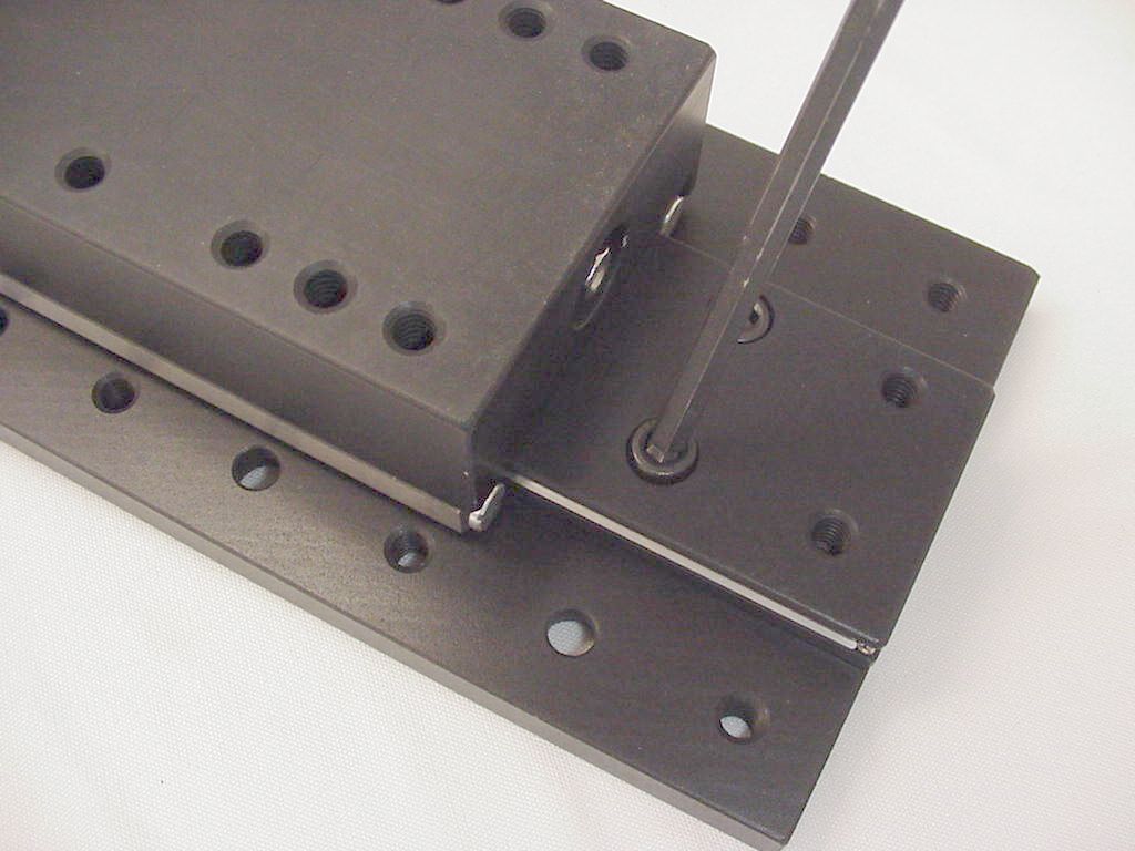
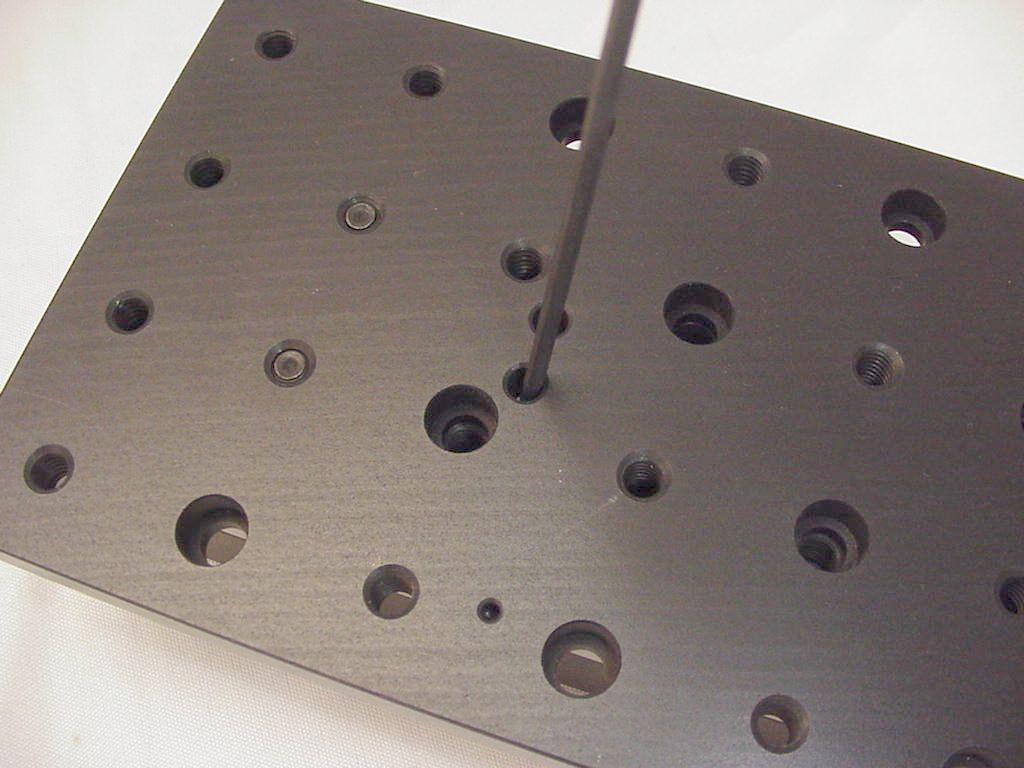
Attaching Optional Slide Mounting Plate
The optional Top Plate contains more ¼-20 tapped holes and ¼ Allen head counter-bores than are available on the stage slider. The additional space is often desirable for attaching other fixtures. The Top Plate can be attached to the assembled LS-stage with minimal disassembly. Counter-bores on each end of the LS stage slider match tapped holes in the Top Plate that can be used for attachment. Using the controller, you can run the stage to both extremes of the travel in turn to access the mounting counter-bored holes. Alternatively you can unscrew the lead screw coupling (2 4-40 screws) allowing the slider to move freely to access the mounting holes. The photos below show the required steps for an LS-100 stage.
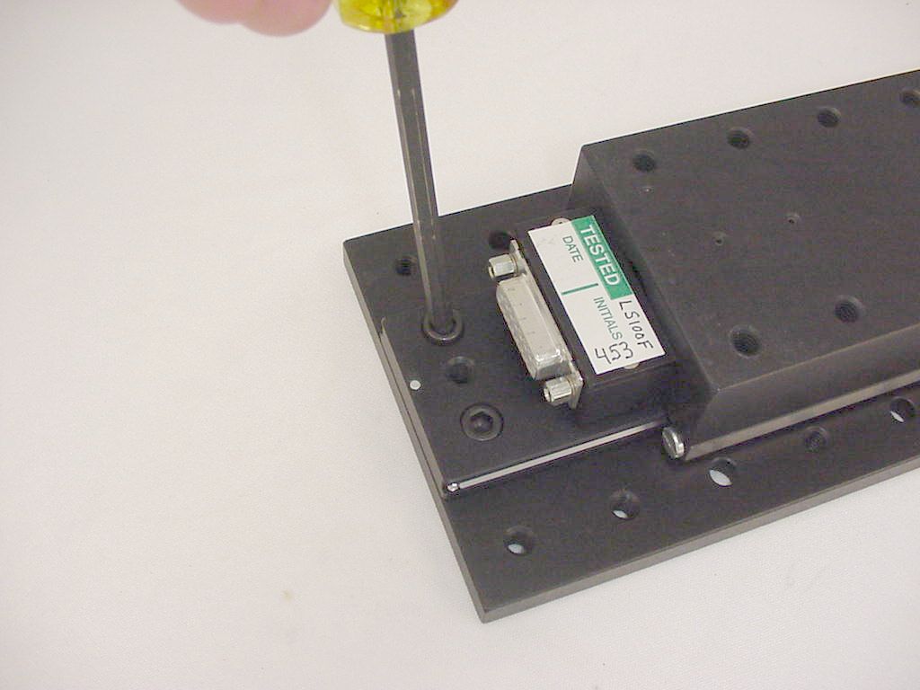
The LS-50 has less travel than the LS-100, so to access the counter-bores on the connector end of the stage, it is necessary to remove the connector housing. This is accomplished by removing the jackscrews on the connector, removing the connector cover, and removing the connector housing screws. Carefully move the connector and wiring out of the way while attaching the top plate screws. Reinstall the connector when completed.
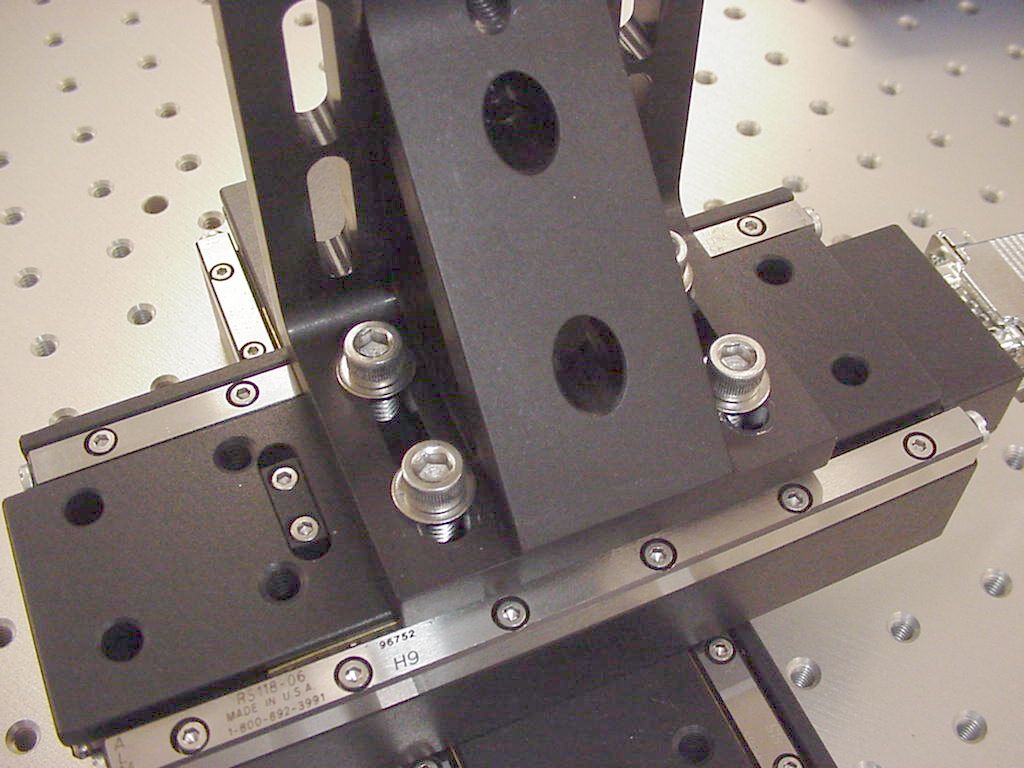
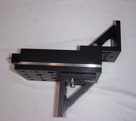
Attaching Optional Angle Brackets
Gusseted angle brackets are frequently used to rigidly couple multi-axis components. The LS-50 top plate has a set of holes designed for center placement of an angle bracket. The LS-stage slider has holes that work well for mounting angle brackets for Z-axis LS-units. The hotos below show some examples.
Cable Connections
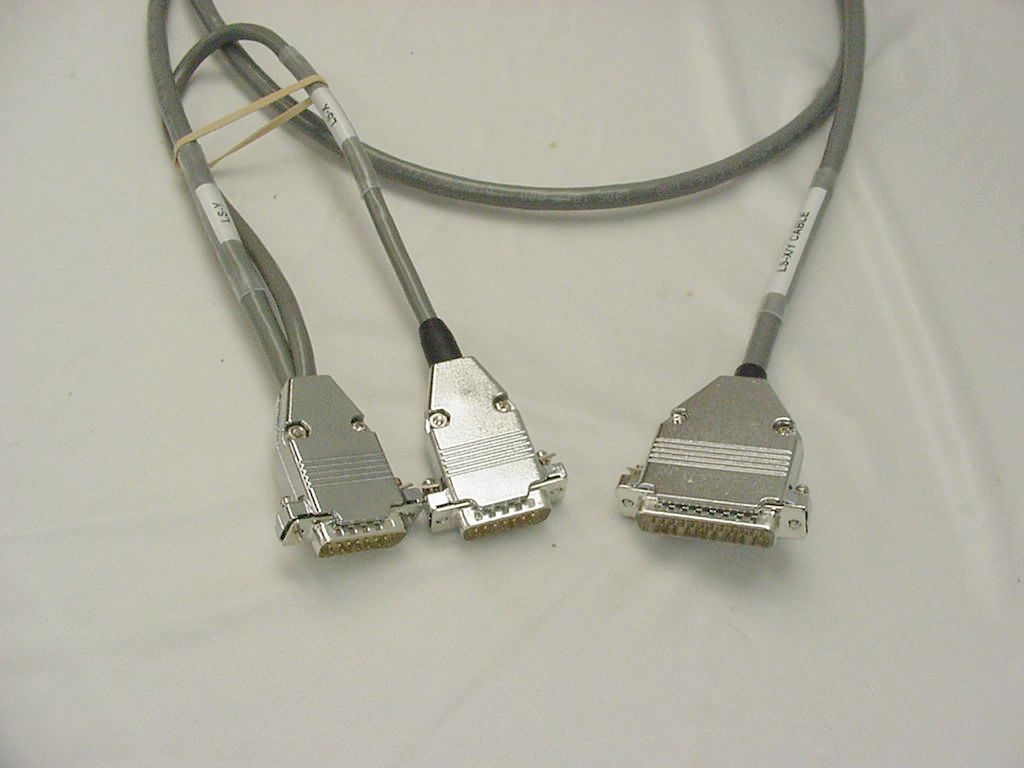
LS stages have a DB15 female connector that attaches to the stage cable.
Dual LS stages that are set up for XY operation utilize a split cable. The X and Y axis connectors are labeled. The other end of the split cable has a DB25 male connector that attaches to the X-Y Stage connector on the MS-2000 controller.
Single Axis systems, Z-axis/Zoom systems, and Z-axis/Theta systems use the Z-Axis Drive connector on the MS-2000 controller. On single axis systems, connect the cable’s DB15 male connector to the LS stage and the DB15 female connector to the MS-2000 controller. Where the Z-Axis Drive connector is used for two functions, special split cables are provided that allow connection to the Zoom motor or Theta stage. In some Z-axis/Theta systems, the theta stage is wired to the Z-axis stage connector.