Table of Contents
Olympus AX 70 Microscope Motor Drive Installation
Motor Drive Installation
This procedure steps you through the installation and alignment of the ASI AX 70 Z-axis motor drive onto the Olympus AX 70 microscope. The following tools are required for this procedure:
small knife or flat blade screwdriver 2.5mm hex wrench (provided) 3.0mm hex wrench (provided) 1/16” hex wrench (provided) 5/64” hex wrench (provided) 3/32” hex wrench (provided) 7/64” hex wrench (provided)
The procedure has three parts:
- Removing the left fine focus knob
- Installing and aligning the motor drive assembly & Baseplate.
- Installing the cover.
Part 1 - Removing the Left Fine Focus Knob
Remove the left fine focus knob from the microscope as follows:
Note: the terms left and right refer to the sides of the microscope as viewed from the front.
- Remove the rubber boot from the end of the left fine focus knob. Then use a knife or small pointed instrument to carefully pry out the 20mm black disk that covers the end of the knob.
- Remove the left fine focus knob by first removing the screw that secures it using the 2.5mm hex wrench then pulling the knob off of the fine focus shaft. It will be necessary to hold the right fine focus knob while removing the screw to prevent the shaft from turning. After the knob is removed, note if there is a small silver spring washer attached to it, if so remove the washer from the focus knob and place it on to the brass assembly located within the coarse focus knob.
Part-2 Installing & Aligning the Motor Drive
Installing the Drive.
The ASI motor drive attaches to the silver horizontal adjustment bar that is attached to the black base plate. The motor drive slides into two lips on either side of the horizontal adjustment bar so that it can slide along the vertical axis and is secured to the adjustment bar via a 4x16mm screw. The horizontal and vertical adjustments allow the drive to be correctly positioned so the drive shaft on the ASI motor drive can be slid over the fine focus shaft of the microscope. The drive and baseplate are installed as a unit and must be assembled / prepared before installing the drive.
a) Locate the Black base plate, the motor drive, the brass clutch plate, and the Allen wrenches. Use the 3/32” Allen wrench to remove the black & silver clamp assembly from the right side of the baseplate. Use the 3mm Allen wrench to loosen the screw securing the adjustment bar to the left side of the baseplate. This is the horizontal adjustment screw. Loosen the screw just enough so that the adjustment bar can slide easily in the groove in the baseplate.
b) Locate the ASI fine focus motor drive and brass clutch plate. Remove the vertical adjustment screw, M4 x 12 hex screw, which is screwed into the left side of the adjustment bar. Rotate the drive plate so that the recesses at the bottom, inside edges of the driveplate align with the keys on the outside edges of the adjustment bar, then press the driveplate towards the adjustment bar until it meshes. Screw in the vertical adjustment screw but leave it just loose enough so that the driveplate can slide up and down. Use the 3 mm hex wrench.
c) Use the 7/64 Allen wrench to loosen the clamp that is located on the ASI drive shaft. This clamp is located at the end of the drive shaft as it protrudes out of the black encoder cover. Once the clamp is loose slide it back towards the encoder and slide the brass clutch plate onto the ASI drive shaft. The clutch plate should slide onto the drive shaft with the milled out portion pointing away from the encoder.
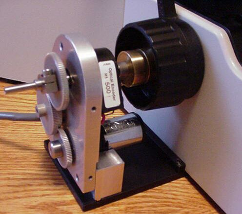
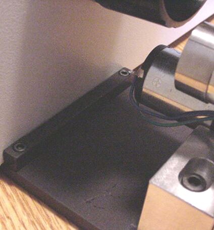
d) As shown in figure 1., slide the ASI drive assembly towards the left fine focus knob of the microscope so that the baseplate slides under the microscope. While holding the right fine focus knob align the ASI drive shaft with the microscope’s fine focus shaft and slide the ASI drive shaft over the microscope’s fine focus shaft. If you do not hold the right fine focus knob the microscope’s fine focus shaft may be pressed over towards the right of the microscope. If this happens simply push the right fine focus knob in towards the microscope to push the shaft back. Push the drive / baseplate assembly completely onto the microscope until the small black stop plate located on the baseplate, as shown in figure 2., is completely against the side of the microscope. This stop plate should be parallel with the bottom of the microscope.
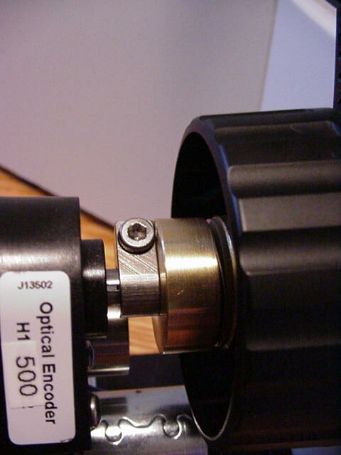
e) While holding the right fine focus knob push the clamp on the ASI focus shaft in towards the microscope so that the brass clutch plate is firmly pressed up against the silver spring washer locate on the microscope’s brass assembly. Please refer to figure 3. Use the 7/64 inch hex wrench to securely tighten the clamp. Note The Clamp Must Be Securely Tightened or the drive and clutch may slip
f) Slide the motor drive up and down, forward and backward slightly while turning the right fine focus knob until it is in the position where minimum drag is felt on the right focus knob. Secure the motor drive into position by tightening the horizontal and vertical adjustment screws.
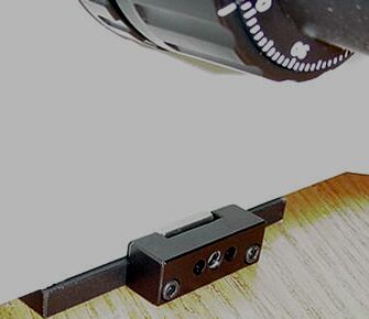
g) As shown in Figure 4., reattach the black & silver clamp assembly to the right side of the baseplate. This clamp assembly was removed in step a). Once the assembly has been reattached use the 5/64” Allen wrench to tighten the set screw located in the middle of the clamp assembly. Tightening this set screw will cause the silver bar to press against the side of the microscope. Insure that the set screw is securely tightened to hold the baseplate assembly in place.
h) Recheck the alignment by noting the drag while rotating the right fine focus knob. No noticeable drag should be felt. If any drag is felt other than the slight drag of the gears loosen the vertical and horizontal adjustment screws with the 3 mm Allen wrench and move the drive in the x,y, and z axis to a point where no drag is felt. Then tighten the vertical and horizontal adjustment screws. Note there should be no point through out the 360º rotation of the fine focus knob where an increase in drag is felt. If drag is felt repeat the above steps.
Part 3-Installing the motor drive cover plate & fine focus knob.
a) Locate the motor drive cover. Position it over the motor drive assembly and secure in place using the 3 small 4/40screws and 1/16” Allen Wrench provided. Do not tighten the screws at this time.
b) Slide the microscope fine focus knob over the shaft extension and press it on all the way. Secure the knob to the shaft with the original 3x8mm socket head screw. Use the 2.5mm Allen wrench to tighten the screw while holding the right fine focus knob. Check to insure the left fine focus knob does not rub against the cover. If it does move the cover and then secure the cover in place by tightening the screws that secure it.
c) Reinstall the black disk and rubber boot that where removed in part one, step one.
This completes the procedure for installing the ASI motor drive on to the Olympus AX 70 Microscope.