Table of Contents
Heidenhain, Renishaw and MicroE XY Linear Encoder Installation
Congratulations on your choice of this option. The Tiger and MS2000 with XY linear encoders offers unparalleled accuracy and repeatability. The encoders used on MS2000 stages are optical devices with a count resolution of 10nm(with Heidenhain and Renishaw ) and 2.5nm(MicroE). In order to give this superb performance, care must be taken in the handling of the encoders, scales, and stage.
Specifications
| Heidenhain Spec | |
|---|---|
| Model | LIF 471 |
| Scale Type | 120mm long glass scale phase grating |
| Signal Period | 4μm |
| Interpolation | ×100 |
| Resolution | 10 nm |
| Accuracy | ±3μm over full travel range |
| Index | Center of travel range |
| Renishaw Spec | |
|---|---|
| Model | T-1000-30A w/ Ti2000 interpolator |
| Scale Type | RGSZ20 gold scale |
| Signal Period | 10μm |
| Interpolation | ×250 |
| Resolution | 10nm |
| Accuracy | ±3μm/m; ±0.75 μm/60mm |
| Index | Near center of travel range |
| MicroE Spec | |
|---|---|
| Model | Mercury II 5800 |
| Scale Type | Laser tape scale with 20um grating period |
| Signal Period | 20μm |
| Interpolation | ×8000 |
| Maximum speed | 125mm/sec |
| Resolution | 2.5 nm |
| Accuracy | ±30nm over 20um travel, ±5μm over 1 meter travel |
| Index | Center of travel range |
Installation
The linear encoders are installed at the factory on your stage. Careful alignment of the encoders has been already done for optimum performance. Please exercise care not to inadvertently bump the encoder heads or to smudge the scales when mounting or using the stage.
The encoder read heads and scales are embedded within the three stage plates. This protects the encoders from contamination and provides for the most reliable operation.
Warnings
- DO NOT remove the encoder heads or the encoder scales from the stage unless you intend to do a complete realignment of the linear encoder.
- DO NOT make adjustments to the trim potentiometers on the encoder electronic modules.
- Please contact ASI if you believe that the linear encoder is not functioning properly.
- Install the stage on your microscope as described previously in this manual.
Connect the encoder read-heads to the correct connectors on the back of the MS2000, RM2000 and Tiger controller. The X and Y encoder cables (with attached electronics) are labeled and should be plugged into the corresponding labeled connectors on the controller.
Switch Settings
DIP SWITCH #3: This switch informs the firmware which encoder is in use. DIP Switch 3 should be DOWN for the linear encoders, UP to use the rotary encoders on the motors. The controller must be reset after changing DIP switch #3 for the firmware to notice the change.
Note: There are no dip-switches in Tiger system, axis is set in LE mode with [Addr#]CCA X=1 for XY and [Addr#]CCA X=3 for ZF. (You can switch back to rotary mode with X=2 for XY and X=4 for ZF)
Maintenance
The linear encoders are holographic devices that view an extended region of the scale at all times. This makes the encoder immune to miscounts due to dust or dirt. Nevertheless, if the scale becomes too dirty, inaccuracy and miscounts can result. Do not get fingerprints on the scale. If the scale becomes dirty, clean with a cotton swab moistened in alcohol. Allow all traces of the solvent to evaporate before using the stage.
Firmware Configuration and Features
The correct firmware configuration is installed at the factory. If the firmware is upgraded I the field, it may be necessary to correctly configure the controller for 10nm and 2.5nm resolution linear encoders. See the CUSTOMA command . After new firmware is installed, the following commands should be issued to the controller:
CCA X=21
RESET
10nm for Heidenhain and Renishaw encoders
CCA X=52
RESET
2.5nm for MicroE encoders
The index on the Linear encoders can be used as an absolute position reference. The user can access this feature using the SI command . The SI command causes the stage to seek the index location and set the absolute coordinate position of the index.
MicroE In-Field Alignment and Adjustment
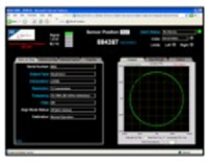
If you wish to align the linear encoders to increase or decrease its resolution, it can be done thru the alignment too shown in figure a (purchased separately). The alignment tool will not only allow you to align the encoder but also to change the encoder resolution between 5um to 1.22nm and, adjust the programmable low pass filter which may reduce the maximum speed but improves noise and stability.
As always feel free to contact us thru support@asiimaging.com or call us at 1-541-461-8181 for further assistance.


