Table of Contents
Zeiss Axiovert 100-135 Series Microscope Z-Drive install Procedure
The instruction steps below describe how to install the ASI motor drive onto the Zeiss Axiovert 100 Series Microscope (left side drive).
The procedure has three parts:
- Preparing the microscope to be inverted and installing the ASI baseplate
- Installing the motor drive assembly onto the baseplate and microscope
- Adjusting the motor drive
The following tools will be required to perform this installation:
- 14mm deep socket wrench
- 3mm hex wrench
- small slotted screw driver
- 4mm hex wrench
- medium phillips screw driver
- 2.5mm hex wrench
- .050 inch hex wrench
- 7/64 inch hex wrench
Part 1 - Installing The Baseplate & Extension Washers
1) This step requires that the microscope be inverted, or raised on its end. Before inverting the microscope, the eyepieces, illuminators, camera, camera tube, tower, and any other components that could be damaged or fall off, must be removed from the microscope. If necessary, refer to your Axiovert manual for instructions on how to remove these items. Briefly, at minimum, the following steps are required:
a.) remove both the UV and tungsten lamp housings by loosening the single screw securing the housing with a 3mm hex wrench.
b.) remove the tower by removing the four screws securing the tower to the microscope with the 4mm Allen wrench. Please note when reinstalling the tower that the two longer screws go on the bottom. Alternatively, the tower may be held in place.
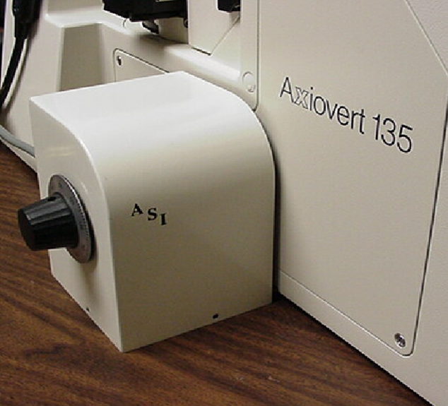
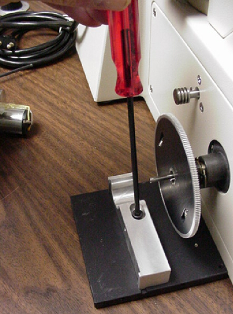
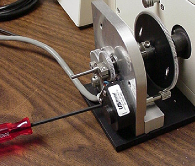
c.) If inverting the unit remove the binocular assembly by loosening the 2.0mm Allen head setscrew that secures it to the microscope. If the eyepieces have not been removed care should be taken to keep them from falling out when handling the binocular assembly. If the microscope is to be laid on its back as shown in figures 1-3 below the binocular assembly and tower do not need to be removed.
d.) The stage and objectives may also be removed to prevent any damage, but this is not necessary
Once the microscope is prepared, it can be carefully lifted, turned over, then placed on its top on a clean, soft surface.


1) Unscrew the two middle screws that secure the black cover to the Microscope.
2) Locate the ASI baseplate. Place it on the bottom of the microscope so the two holes in it aligned with the threaded holes in the microscope base. Secure it in place with the two flathead screws provided.
3) If needed loosen, but do not remove, the two adjustment screws on the bottom of the ASI base plate. Then slide the back base plate up against the microscope body until it is flush and parallel with the microscope body as shown in figure 4 below.
4) Re-invert the microscope by carefully picking it up and turning it over.
Part 2 - Installing the Drive Assembly
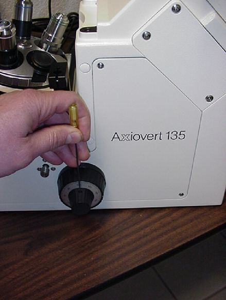
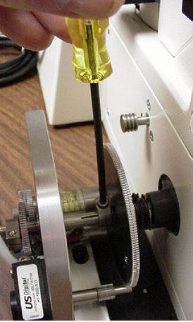
1) Remove the left fine focus knob from the microscope by loosening the setscrew in the side of the knob using the .050 inch hex wrench, then slide the knob off the shaft.
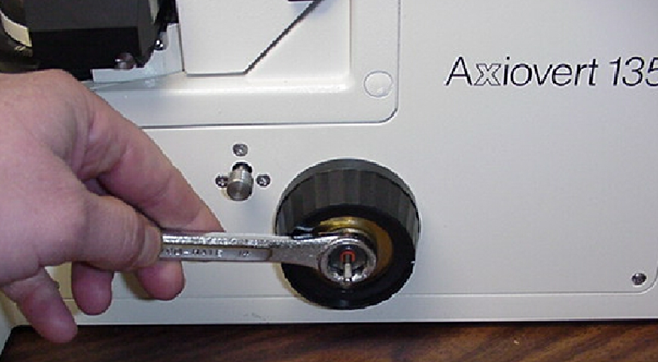
2) Remove the left coarse focus knob by first removing the nut using the 14mm deep socket provided, then unscrew the coarse focus knob. The nut and knob turn counter-clockwise to unscrew. It will be necessary to grip the right coarse focus knob for this procedure to prevent the coarse focus shaft from turning. Once the knob is removed, be careful not to disturb the exposed stop rings on the coarse focus shaft.
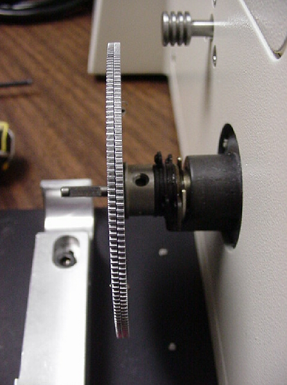
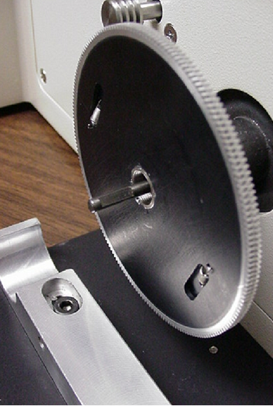
3) Locate the anti-backlash gear included with the ASI motor drive components. Screw it onto the threaded bushing from which the coarse focus knob was removed. Orient it so that the protruding (shiny) part of the threaded bushing faces the microscope. Tighten it firmly by rotating it clockwise while gripping the right coarse focus knob.
4) As shown in figure 6 Loosen the screw in the rectangular block attached to the baseplate so that the block can slide easily in the groove. Remove the vertical adjustment screw located in the side of the block. Locate the ASI motor drive assembly.
During the next part of this procedure, the drive assembly will be positioned so that the drive shaft slips over the microscope fine focus shaft and the smallest gear of the drive assembly meshes with the large anti-backlash gear.
5) Rotate the anti-backlash gear so that the two blackened teeth are visible. Now rotate the gear half that faces towards the microscope so that the two blackened teeth are aligned. Hold the gear halves in this position.
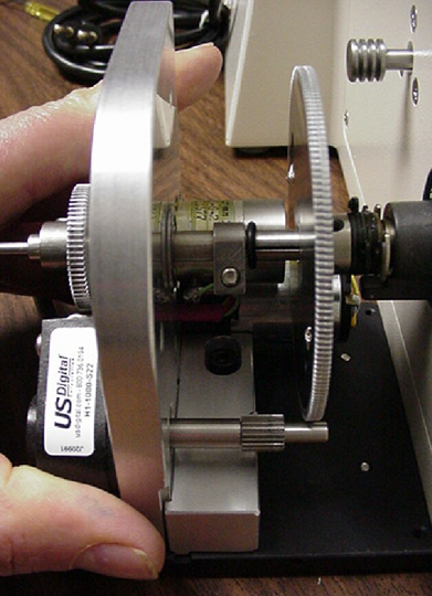
6) Now, position the drive assembly so that the hollow drive shaft slips over the microscope fine focus shaft. Maneuver the drive assembly in towards the microscope until the smallest gear approaches the anti-backlash gear. Continue to move the drive assembly in towards the microscope while rotating it slightly about the axis of the fine focus shaft until the two gears mesh. Tension can now be released from the two halves of the anti-backlash gear. Check to see that the two blackened teeth are still aligned. If not, repeat step 5 and this step. If the smallest gear does not fully engage with the anti-backlash gear, loosen the setscrew securing it to the shaft using the .050 hex wrench and slide it into a position that assures that the gears fully engage. If this adjustment is necessary, be sure that the two blackened teeth on the anti-backlash gear remain aligned.
7) Next, rotate the drive assembly slightly until the edge grooves at the bottom towards the microscope are aligned with the mating surfaces on rectangular block. Press the drive assembly onto the rectangular block.
8) Insert and thread in the vertical adjustment screw, but do not tighten it yet.
Part 3 - Aligning the Drive Assembly
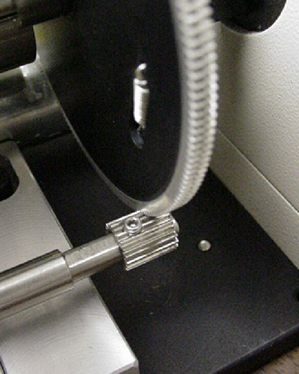
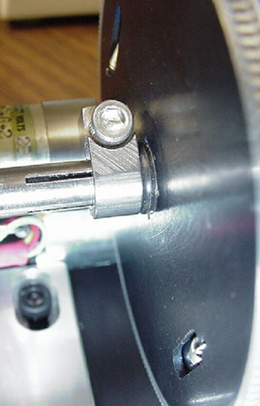
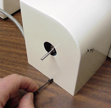
1) Press in on the drive shaft to make sure it is fully over the microscope fine focus shaft. Center and tighten the clamp on the end of the drive shaft towards the microscope using the 7/64 inch hex wrench as shown above. Check the alignment of the drive shaft gear with the outer of the two gears on the clutch. If these gears do not mesh accurately, loosen the clamp on the drive shaft gear using the 7/64 inch hex wrench. Position the gears so they are in exact alignment. Tighten the gear clamp. Recheck the alignment by turning the right fine focus knob. If an increase in friction is felt repeat step #1.
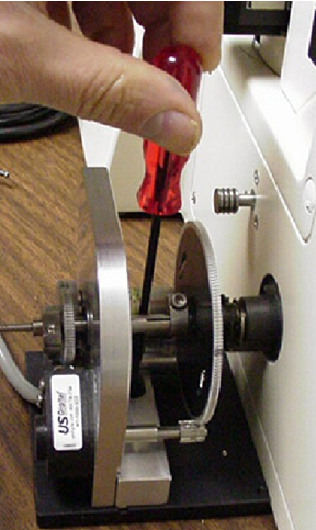
2) Align the drive assembly to the microscope by carefully sliding it up and down, forwards and backwards slightly, while rotating the right fine focus knob. Alignment will be optimum when minimal friction is felt as the right fine focus knob is turned. Hold the drive assembly in this position. Tight the horizontal and vertical adjustment screws. Recheck the alignment. Repeat this step if necessary.
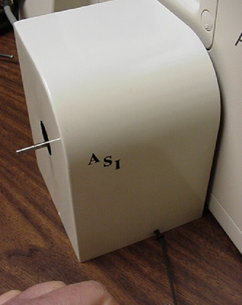
3) Remove the screws located in the edges of the baseplate. Locate the ASI drive assembly cover. Position the cover over the fine focus extension shaft and motor drive assembly. Make sure the blue drive cable comes out under the grommet at the back. Please note that the access hole on the back of the cover allows one access to the camera target knob. Secure the cover in place with the three screws just removed.
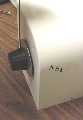
4) Slide the microscope fine focus knob over the shaft extension. Secure it in place by tightening the set screw in the side of the knob using the 0.50 inch hex wrench.
The eyepieces, illuminators, camera, camera tube, tower, and other components that were removed in Part 1, Step 1 can now be reinstalled on the microscope. This completes the procedure for installing the ASI motor drive assembly to the Zeiss Axiovert microscope.