Table of Contents
SCAN MODULE Sync and Scanning Addendum
Raster and serpentine scanning has been made simple and flexible with some special firmware and hardware options added to ASI's standard controller. Raster scanning is often used in conjunction with other equipment which collects data during the scan, the goal being data generation that can be mapped accurately in the two spatial scan dimensions. To facilitate this, the ASI controller with SCAN_MODULE firmware provides one or two TTL signals that are clocked to positional references. These signals are wired from the axis chosen by the customer when the controller is manufactured.
The first signal, SYNC, provides a “start-of-line” reference signal that occurs as the stage scans across a predetermined position for every raster-scanned line. Users can use the SYNC line and constant stage speed along with uniform data sampling to achieve imaging synchronization. The controller can keep the stage speed very constant with no accumulated error (on target to within a few encoder counts throughout the scan), so accompanied with a uniform sampling interval, accurate pixel rendition is possible without directly triggering the acquisition from the controller.
Three firmware options are available that involve how the TTL_IN interrupt is handled, IN0_INT, ENC_INT, and ENC_INT_2.
IN0_INT
The basic SCAN_MODULE operation offers only the SYNC output from the controller. It is supplied with the IN0_INT firmware module which allows all of the normal TTL input functions to be available (described by the X-parameter options for the TTL command). For TG-1000 “Tiger” controllers the SYNC signal is available on the backplane and can be exposed easily using the Tiger Programmable Logic Card. The ENSYNC command can change the trigger position of the SYNC signal, the default position is 0.
Large parts of this document describe functionality of the ENC_INT and ENC_INT_2 modules and do not apply to the SYNC modality.
ENC_INT
The ENC_INT firmware module outputs a pixel clock corresponding exactly with stage motion. Normal TTL input functions are not available. It is only recommended for stages using a rotary encoder.
With the ENC_INT firmware module and wiring, one channel of the stage encoder is routed to the microprocessor's interrupt input. The controller counts down encoder pulses and sends a output pulse on the TTL_OUT BNC connector after the programmable number of N encoder counts have gone by. In this way, the TTL_OUT signal can effectively be the pixel clock of the data acquisition system, where the user can program the distance between pixels. Note that ENC_INT does not work reliably with linear encoders. The distance between pulses must be a multiple of 4 encoder counts.
ENC_INT_2
The ENC_INT_2 firmware module works with both rotary and linear encoded stages. It outputs a pixel clock corresponding exactly with stage motion. Normal TTL input functions are not available.
With the ENC_INT_2 firmware module and wiring, pulses (on the Enc÷N BNC port) with the rising edge aligned to the exact moment when the stage's selected axis crosses the pre-calculated subdivision points during the scan. In this way, the TTL_OUT signal can effectively be the pixel clock of the data acquisition system, where the user can program the distance between pixels. The distance between pulses is specified as a multiple of the encoder count.
The advantage of ENC_INT_2 is that it ignores any encoder jitter, which enables this module to be used with linear encoders. The disadvantage is that it does not work if the output pulses come faster than 4KHz. With 10nm linear encoders, the speed limit calculates to (0.04mm/s * enc_divide), so if the enc_divide variable (SCANR Z) is set to 100 (every 100 encoder counts, or 1um), then the maximum SPEED with ENC_INT_2 would be 4mm/s. To be able to generate pulses every 100nm, then the maximum scan speed would be 0.4mm/s.
All the basic commands are the same between ENC_INT and ENC_INT_2.
Required Firmware Modules
To check if the controller has the required firmware modules, send the serial command BUILD X to query the controller (prefix the card address on Tiger).
There are 2 modules required to enable scan functionality:
SCAN_MODULEIN0_INTorENC_INTorENC_INT_2
Required Hardware Modifications
Tiger Card
The default hardware configuration only supports IN0_INT, the SCAN_MODULE requires a hardware modification to use either ENC_INT or ENC_INT_2.
The ENC_INT or ENC_INT_2 modifications are mutually exclusive. There are 3 hardware configurations:
- Default Hardware -
IN0_INT - Modification A -
ENC_INT(requires hardware modification) - Modification B -
ENC_INT_2(requires hardware modification)
MS-2000
The default hardware configuration only supports IN0_INT, the SCAN_MODULE requires a hardware modification to use either ENC_INT or ENC_INT_2.
The ENC_INT or ENC_INT_2 modifications are mutually exclusive. There are 3 hardware configurations:
- Default Hardware -
IN0_INT - Modification A -
ENC_INT(requires Board Jumpers)- Also required for the
SV1 Pin 7 (Line Sync)signal inIN0_INTbuilds.
- Modification B -
ENC_INT_2(requires Board Jumpers and hardware modification)
These modifications should be performed by ASI, please contact us for assistance.
Scan Module Basics
Use the commands SCAN (SN), SCANR (NR), and SCANV (NV) to configure the scan parameters such as start and stop positions in both the scan and other axis, which axis has which role, the number of lines, etc.
See the programming section for a full description of these commands, but this is a “quick start” guide.
NR X and NR Y sets up the raster scan start and stop positions in units of millimeters. The retrace speed can be specified using NR R in some firmware builds only. NR Z and NR F set up the divider and number of pixels and only apply to the ENC_INT module.
NV X and NV Y set up the start and stop positions in the “vertical” (non-scan) direction in units of millimeters. NV Z specifies many scans to perform (they will be evenly spaced in the “vertical” axis). NV F configures how much overshoot is applied along the scan axis to ensure that the stage is up to speed before it passes the scan start position where a SYNC pulse is generated.
SN without arguments is used to initiate the scan. SN F selects between raster and serpentine patterns, and which axis does which motion can be specified using SN Y and SN Z commands.
Raster and Serpentine Scanning
The user can select either Raster or Serpentine scanning modes using the SCAN F=mode command. During a Raster scan, the active scan begins at the same edge for each line, and is followed by a high speed retrace movement at the end of the scan line. For a Serpentine scan, the scan proceeds first in one direction, then in the opposite direction, advancing vertically one line each time the direction changes (there is no retrace movement). The “start-of-line” reference position is moved from one side of the scan area to the other depending upon the direction of the scan.
Raster scanning has the advantage that system backlash will be negligible, since the motion is always in the same direction. Serpentine scanning has the advantage of faster coverage (since there is no retrace operation) when very high accuracy is not required.
Encoder SYNC Hardware (ENC_INT only)
The encoder sync pulse is obtained directly from the encoder counting chip inside the controller. This encoder chip can be loaded with a “compare” position, so that whenever the current encoder count is equal to the “compare” count, a flag pin on the chip becomes active. We add additional circuitry to latch the sync pulse during the active part of the scan.
Pulses for the pixel clock are derived from a processed signal coming from the controller's microprocessor (Encoder Divide-by-N) on the normal TTL_OUT BNC connector. The pulses from the encoder are sent to an interrupt line on the controller's microprocessor. The interrupt causes a programmable counter to count down. When the counter reaches zero, the microprocessor sends a pulse to the TTL_OUT connector. These pulses are only enabled during the active scan line.

Board Jumpers
Either the X or Y-axis can be used as the fast raster axis for scanning. Jumpers on the main controller card are used to select the appropriate wiring. The firmware defaults with the X-axis as the fast axis. When configured at the factory, the jumpers are set for a fast X-axis.
MS-2000 Board Jumpers

| MS-2000 Board Jumpers | Fast Axis | ||
|---|---|---|---|
| Function | Jumper | X | Y |
| Sync Flag | JP1 | 1-2 | 2-3 |
| Encoder Pulses | JP2 | 1-2 | 2-3 |
| MS-2000 Jumper Requirements | ||
|---|---|---|
| Firmware Module | JP1 | JP2 |
IN0_INT | optional | not used |
ENC_INT or ENC_INT_2 | required | required |
SCAN firmware versions that have the IN0_INT module rather than the ENC_INT module should leave JP2 unconnected since encoder pulse counting is not enabled in these versions. The ENC_INT module provides the interrupt service handling so the encoder pulses can be counted. The internal interrupt service must be enabled using the TTL command, TTL X=1.
Note: IN0_INT requires the JP1 jumper to output the SV1 Pin 7 (Line Sync) signal on the connected BNC, this requires the MS-2000 Scan Module Hardware Modification A.
MS-2000 SV1 Wiring
The output signals are found on header SV1. SV1 Pin 2 is the Encoder Divide-by-N output and SV1 Pin 7 is the Line Sync output. These pins should be connected to BNC connectors on the rear of the controller. Controllers not specifically set up for the SCAN firmware will usually have SV1 Pin 2 connected to the TTL_OUT BNC and SV1 Pin 1 connected to the TTL_IN BNC. In that case, switch the wire from Pin 1 of the connector over to Pin 7 so that the Line Sync will appear on the TTL_IN BNC.
| MS-2000 SV1 Wiring | ||
|---|---|---|
| BNC | Standard | Scan Module |
TTL_IN | SV1 Pin 1 | SV1 Pin 7 (Line Sync) |
TLL_OUT | SV1 Pin 2 | SV1 Pin 2 (Encoder Divide-by-N) |
Tiger Board Jumpers (TGDCM2)
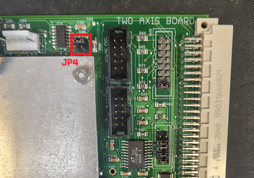
JP4: the top two are shorted for X-axis as the fast axis, the bottom two are shorted for Y-axis as the fast axis. The SYNC signal is available on the backplane and can be exposed using the Tiger Programmable Logic Card.
Example: Ouput the stage card SYNC signal on BNC3 of the PLogic card.
Stage: card address 1, PLogic: card address 6, axis E
M E=35 # set pointer position to front panel BNC3
:A
6CCA Z=46 # set source address to backplane TTL5 (stage sync signal)
:A
1SCANR X=10 Y=50
:A
1SCAN
:A
Using the SCANR, SCANV, and SCAN Commands with ENC_INT or ENC_INT_2 modules
To perform a scan, you must first define the scan region, the pixel clock resolution, and the number of scan lines. The serial commands SCANR, SCANV, and SCAN let the user define the scan region, the scan mode, and initiate the scan process. See an earlier section of this document for a brief description of these commands.
Let’s go through an example where we wish to scan a 1 mm × 1 mm region at a resolution of about 0.5 μm on an XY stage. We will consider the X axis to be the ‘horizontal’ direction, and Y to be the ‘vertical’ direction. (Although any axis is eligible to be ‘horizontal’, only one will have been wired at the factory for encoder output signals – see the SCAN command’s parameters for alternative configurations.) For a standard 6.35 mm pitch lead-screw stage, the (rotary) encoder resolution is 45396 counts/mm or 0.022 μm/count. However, this includes all of the quadrature edges of the two encoder channels and the counting circuit is only looking at the positive edges of one encoder signal, so the input clock pulse to the controller would be at 0.0881 μm intervals. Hence the output clock pulse can only be set to be an integer multiple of 0.0881 μm which is 4 encoder counts (for 4 TPI leadscrew with rotary encoders; if you are not sure of the encoder resolution of the scanned axis, issue the command INFO X, where X is the axis in question, to query the controller about the parameters that are used.). This 0.0881 μm distance (or equivalent [4000/C]) is multiplied by the SCANR Z setting to get the distance between output clock pulses. The maximum output clock would is with SCANR Z set to 8, or just over 176 nm.
If we generate a clock pulse every 24 encoder counts (6 full periods of a single encoder signal), then our pixel clock resolution will be 0.022 × 24 = 0.528 μm. To set up the ‘horizontal’ raster, we issue the command:
SCANR X=0.0 Y=1.0 Z=24 (X= start, Y= stop, Z=encoder_divide)
The command above will generate a scan line with 1891 pixels, determined by multiplying the encoder resolution by the length of the scan and dividing by the encoder_divide parameter. If you wish to specify exactly the number of pixels you want to have in a scan row, you may issue the command using the F = # of pixels, instead of Y = stop_positon.
For the ‘vertical’ direction, if we want square pixels, then we will need 1891 scan lines as well. To set up the ‘vertical’ scan, we issue the command:
SCANV X=0.0 Y=1.0 Z=1891 (X=start, Y=stop, Z=number_of_lines)
In both commands, parameters “start” and “stop” are measured in millimeters from the current origin (“Zero” position where X=0.0mm, Y=0.0mm), and negative values are allowed. The origin can be changed with the HERE command.
Next, we need to determine the correct scan speed based upon the processing time for each pixel. If we assume a 1ms time for each pixel, then we would want to scan at a rate of 0.528 μm/ms or 0.528 mm/s. To set this up for the X-axis we issue the command:
SPEED X=0.528
We can specify that the scan mode will be a raster scan using the command:
SCAN F=0
Finally, we need to turn on the encoder interrupt with the TTL command:
TTL X=1
Note: On MS-2000 v9.53 and Tiger v3.53 firmware, the encoder interrupt is always on and TTL X cannot be changed.
To verify, enter TTL X? and you should see the response :A X=100 if the TTL X=1 command is not required.
Once all of the scan parameters are set up the way we want them, it is possible to save them to non-volatile memory so that we do not need to re-enter them each time we power up.
The command to save settings is:
SS Z
When ready to initiate the scan, issue the command:
SCAN
to start the process. Alternatively, you can use the @ button on the controller to start and stop the scan. To start a scan, hold the @ button down for more than 1 second. When you release the button the scan will start. To abort a scan in process, momentarily depress the @ button.
Limitations and Internal Operation of the SCAN module (ENC_INT / ENC_INT_2 only)
During set-up for a scan, the number of horizontal pulses (pixels) is calculated. During the scan, pulses are counted until the requisite number has gone by. Further interrupts are disabled and the current encoder position is read in. If the current position is not consistent with the expected position based upon the number of pulses and the encoder counts between pulses, an error code is placed in the error log.
The internal data size for certain variables limits the acceptable range of some parameters. For ENC_INT, the encoder-divide parameter and the total number of pixels per scan line must be less than 32768. For ENC_INT_2, the encoder-divide and pixels-per-line can be as high as 65534.
With the MS2000 controller, internal jumpers JP1 and JP2 are used to select either the X-axis (jumper positions 1-2) or the Y-axis (jumper positions 2-3) as the fast scanned axis. Controllers are shipped with the X-axis as the default fast raster axis. Please see the SCAN command to change the default axes for the scanning algorithms. Only the X (default) or Y axis may be used when generating the hardware encoder synchronization TTL pulses. The firmware controlled scan patterns can be used on X or Y, however internal errors (code 85 & 86) will be generated if the proper internal signals are not present or jumped correctly.
For ENC_INT, encoder-divide values are rounded to the nearest fourth, E.G. 1, 4, 8, 12, etc.. For ENC_INT_2, no such rounding occurs and any number between 1 and 65534 is usable for encoder-divide, presuming the speed for the scan axis has been set low enough for small encoder-divide numbers.
For ENC_INT_2, there is a maximum pulse output rate of 4KHz, which corresponds to a maximum velocity of 0.04mm/s * encoder-divide on 10nm linear encoders. The equation for maximum scan speed with ENC_INT_2 is: \begin{equation}S <= \frac{4000 * EncoderDivide}{counts/mm}\end{equation}
Any speed less than or equal to this value will work.
SCAN with Z-Stages
It is possible to use the SCAN_MODULE with ASI Z-stages such as the LS-50.
When using ENC_INT_2 make sure that you set SCANV X=0 Y=0 Z=1, otherwise the Encoder Divide-by-N signal will stay high after the scan is completed.