Table of Contents
Olympus MVX 10 Z-Axis & Zoom Drive Installation Procedure
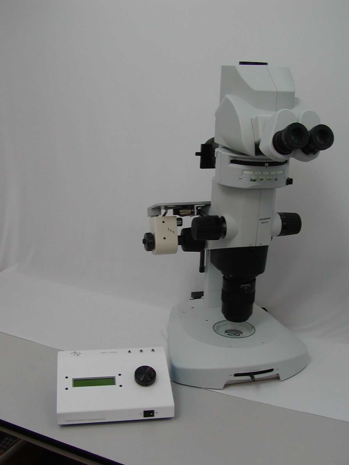
The procedure below outlines the steps necessary to install the ASI Microscope Focus Controller Drive onto the Olympus MVX 10 microscope.
To perform the following steps you will need the following tools:
Flat & Phillips screw drivers & a pair of Pliers 1.5mm, 2.5 mm, 3mm, 1/16 and 7/64 inch hex wrenches Small piece of Emory cloth The hex wrenches are provided by ASI.
The procedure has 6 parts:
- Removing the Objectives, Trinocular head & Fluorescence illuminator to reduce weight when installing the drive assembly
- Removing the left fine focus & the zoom knob
- Installing the base plate & motor drive assembly
- Aligning the motor drive assembly
- Installing & aligning the Zoom belt drive
- Installing the motor drive cover plate & fine focus knob
- Connecting the cables to the controller
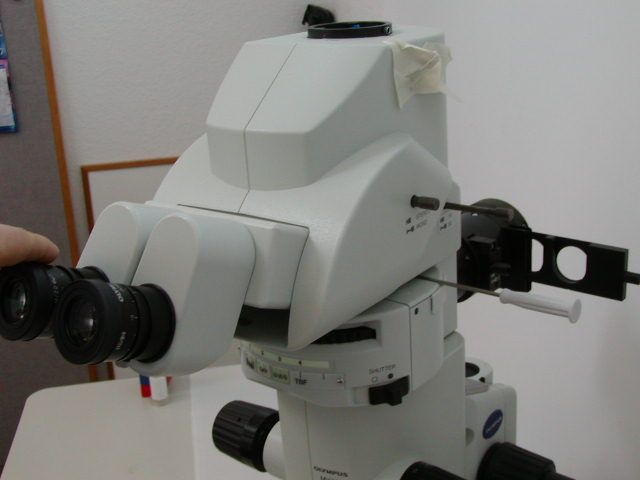
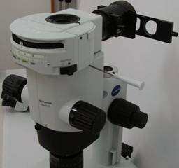
Part 1- Remove the Objectives, Trinocular head & Fluorescence illuminator to reduce weight when installing the drive assembly
If necessary, please refer to the Olympus manuals for this microscope.
Part 2 - Removing the Left Fine Focus Knob (FFK)
Remove the left fine focus knob from the microscope as follows:
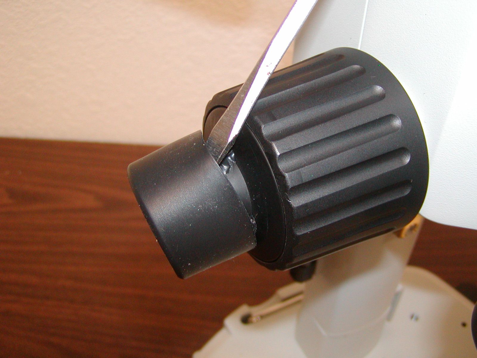
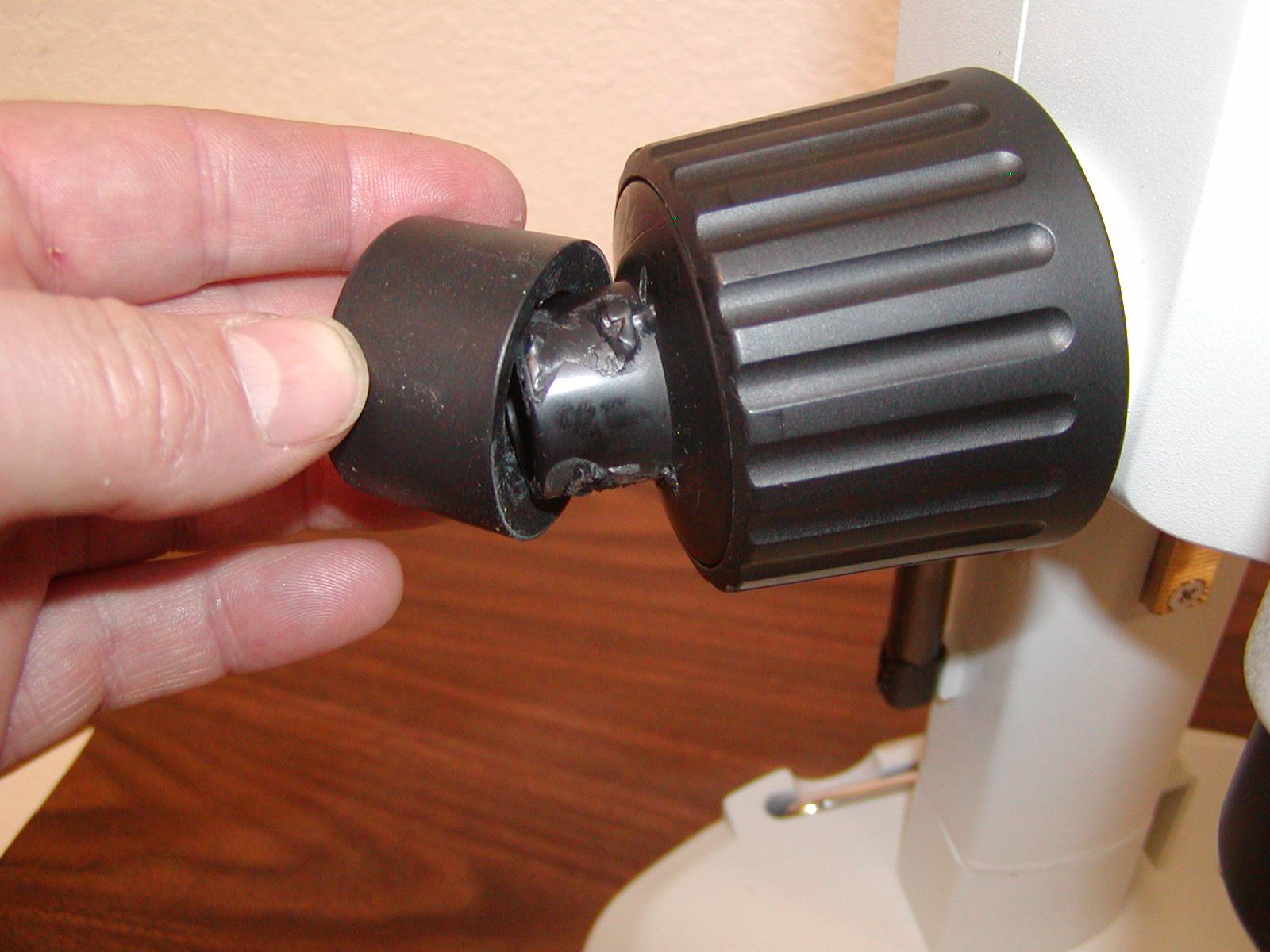
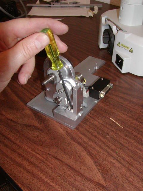
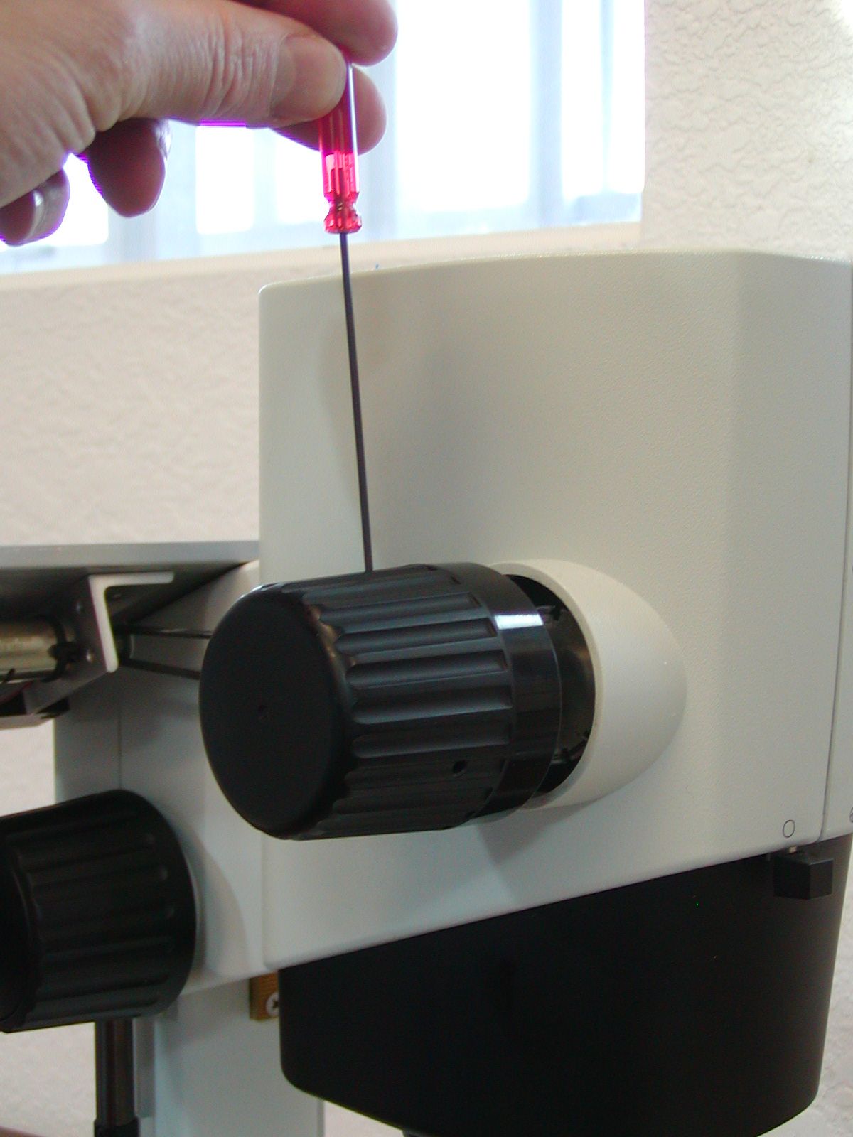
Pry the rubber boot of the end of the left fine focus knob (ffk), on some scopes a screwdriver may be needed to pry the knob off as it may be glued on.
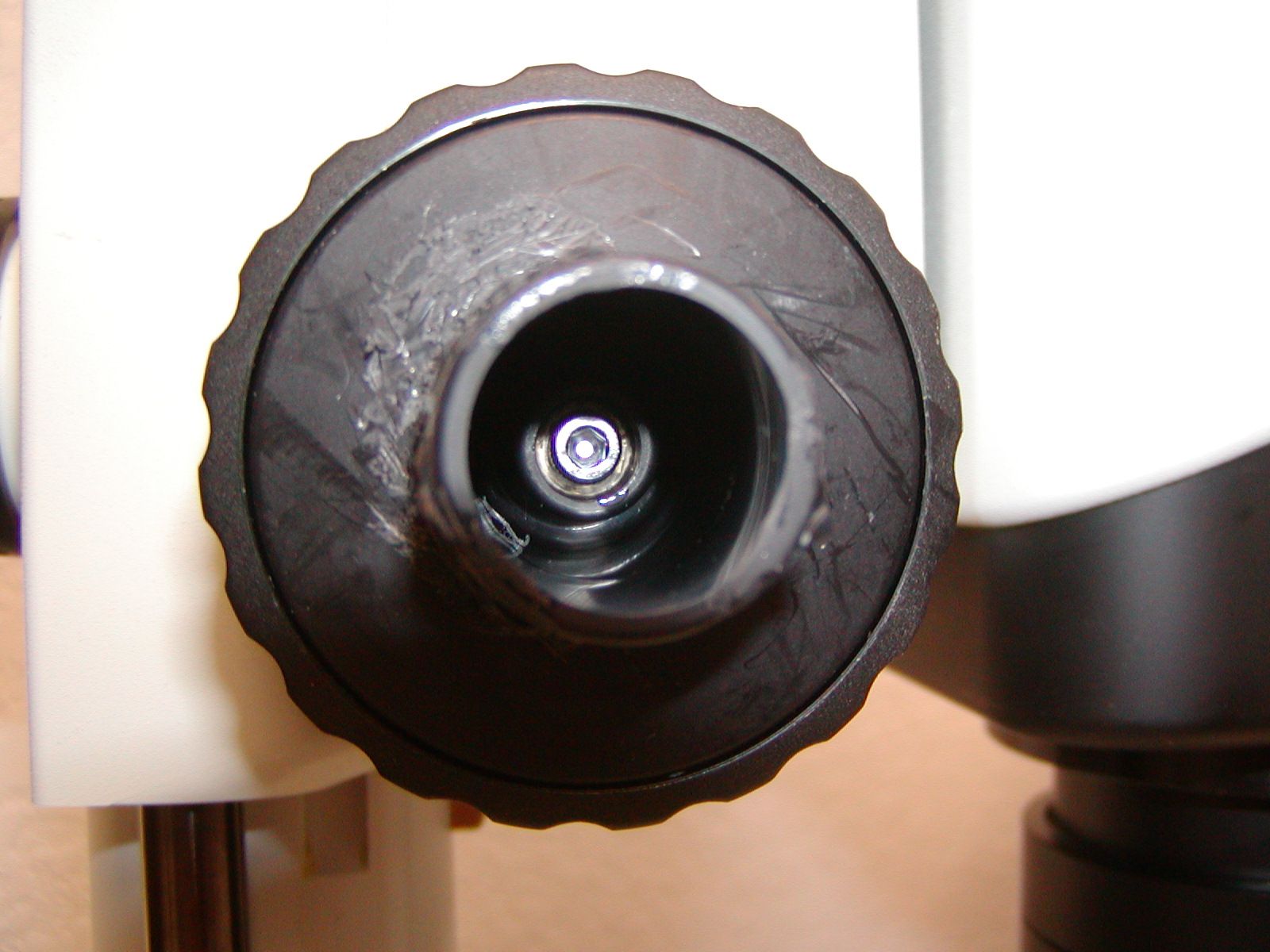
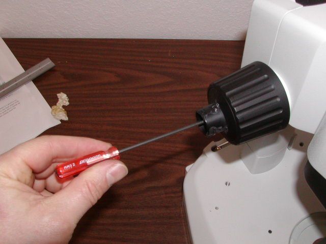
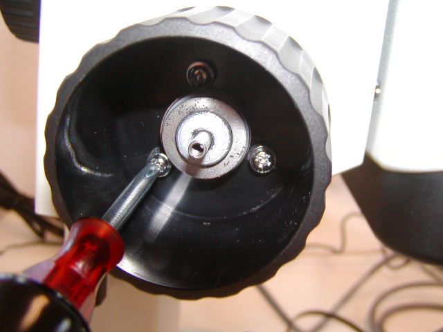
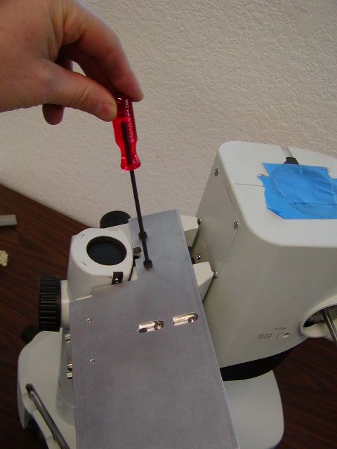
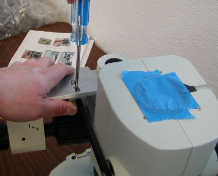
Figure 3 shows the location of the 3x 8 mm screw that must be removed / loosened to remove the ffk. Use the 2.5 mm Allen wrench to remove the screw while holding, or turning, the right fine focus knob.
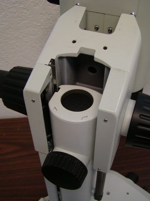
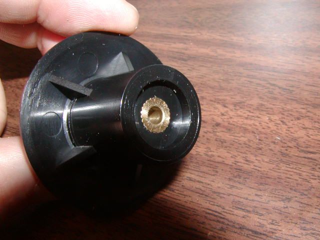
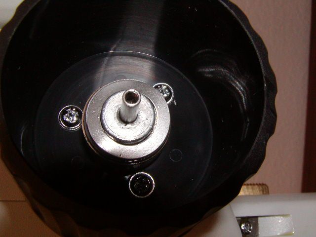
Unscrew the screw that secures the ffk & remove the knob as shown in figure 5. The focus assembly will rise up when the ffk is removed as shown in figure 4. Insure that the two spring washers remained inside of the coarse focus knob as shown in figure 5. If they are stuck to the FFK remove them and place them inside of the coarse focus knob as shown. Store the ffk & 2.5 mm screw that retained it, as they are not needed with the ASI Z-drive.
Installing the ASI Fine Focus Shaft Extender (FFSE)
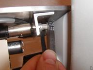
Use a cross blade screwdriver to loosen the three Philip head screws and remove the coarse focus knob as shown in figure 6.
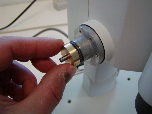
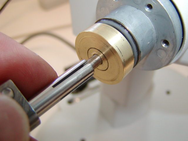
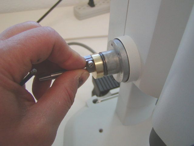
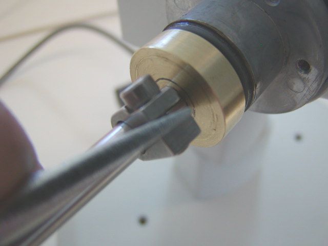
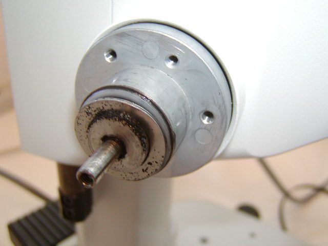
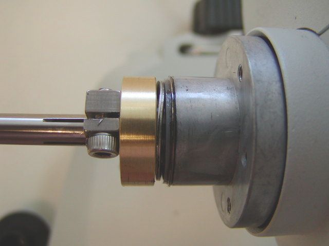
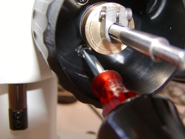
Locate the brass clutch plate & Fine Focus Shaft Extender (FFSE) and install them as shown in the above photos a through d. Note that the clamp & clutch plate must compress the wave washers as shown in photo c. This is done by firmly pressing the clamp & clutch plate against them. You may have to open the clamp up a little bit with a flat blade screw drive as shown in photo d.
Locate the brass clutch plate & Fine Focus Shaft Extender (FFSE) and install them as shown in figure # 7, photos a through d. Note that the clamp & clutch plate must compress the wave washers as shown in figure # 7 photo c, and figure # 8 below. This is done by firmly pressing the clamp & clutch plate against them. Please note; you should insure that the right fine focus knob is presses all the way in against the microscope when doing this. Please also note, that you may have to open the clamp up a little bit with a flat blade screw drive as shown in photo d.
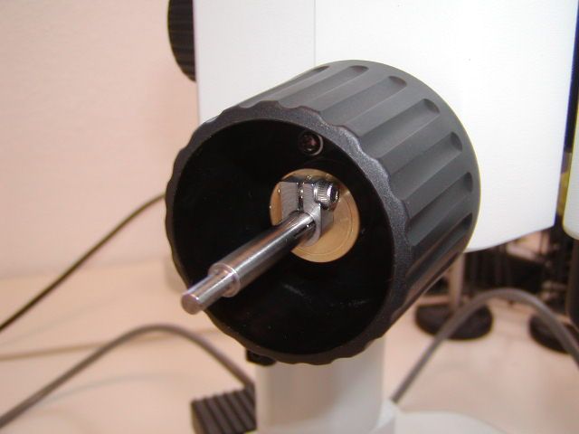
Install coarse knob that was removed in figure #6 as shown above in figure # 9.
Part 3 - Installing the Baseplate & the Z-axis drive
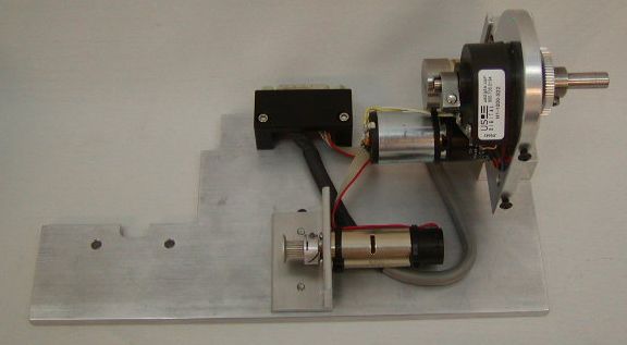
Locate the motor drive and base plate assembly as shown in figure 10. Use the 7/64 “mm Allen wrench to loosen the horizontal & vertical adjustment screws to screws as shown in figures 11 &12. Loosen the drive shaft clamp as shown in figure 13.
Locate the two 4 x 10 mm screws that secure the base plate to the microscope & the 3 mm Allen wrench.
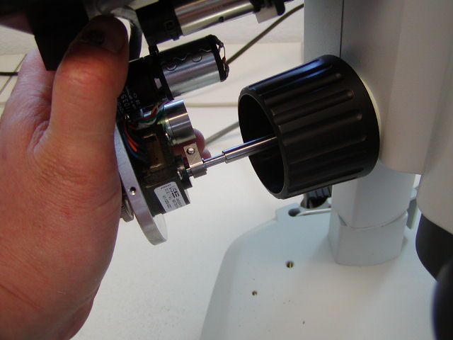
Install the drive assembly as shown. Note that the drive shaft slides over the ffk extender shaft as shown in figure 15. Use the two 4x 10 mm socket head cap screws to secure the base plate to the microscope as shown in figure 16.
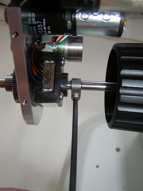
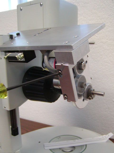
After attaching the motor drive & base plate to the microscope use the 7/64“ Allen wrench to tighten the drive shaft clamp as shown in figure 17. Please note that this clamp must be securely tightened to prevent any slippage. After tightening the drive shaft clamp loosely tighten the vertical and horizontal adjust adjustment screws as shown in figure 18. Do Not overly tighten the vertical and horizontal adjust adjustment screws. The drive may wobble a small amount when driven, and this is normal.
Part- 4 Aligning the Motor Drive
Check the alignment by noting the drag while turning the right fine focus knob. No noticeable drag should be felt at any point with in the full 360 degrees of rotation. If any noticeable drag is felt loosen the Vertical & Horizontal adjustment screws and reposition the drive to a point where no drag is felt. Then hold the drive in place and loosely tighten Vertical & Horizontal adjustment screws.
Part 5- Installing and aligning the Zoom motor drive assembly
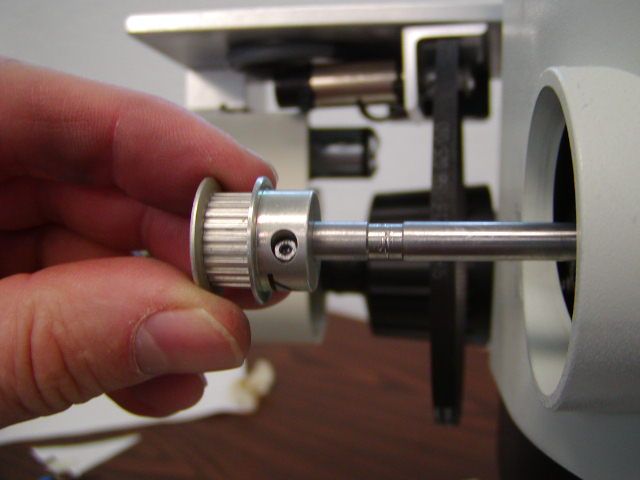
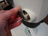
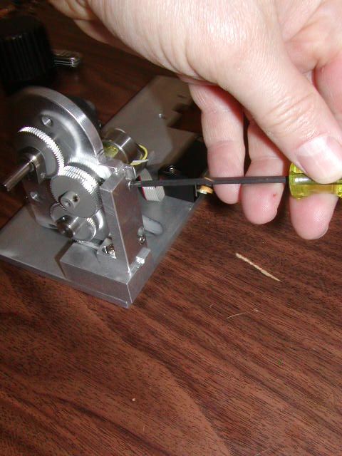
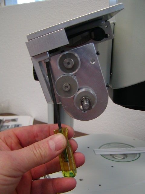
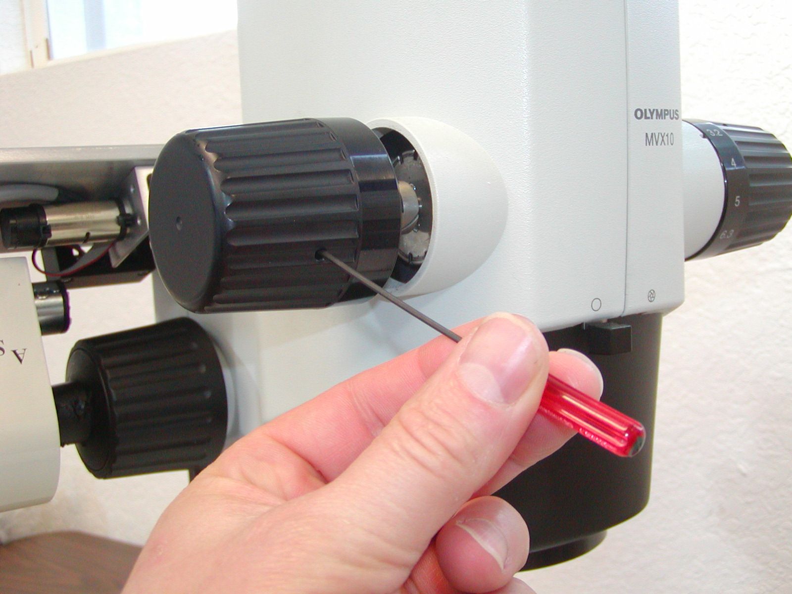
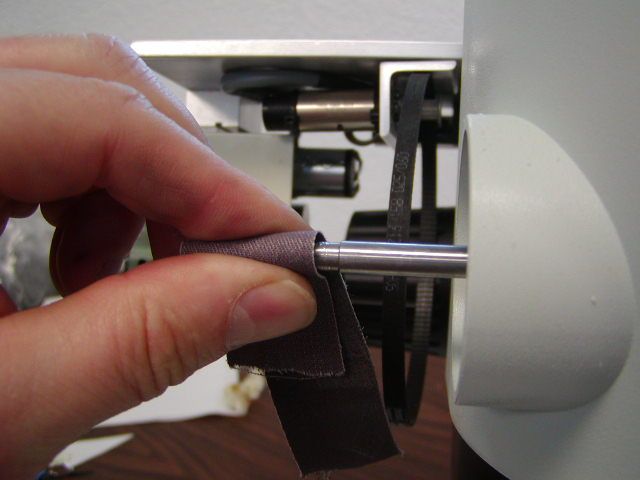
As shown in figure 19 use the 1.5 mm Allen wrench to loosen the two setscrews that secure the left zoom knob on to the microscope & remove the knob. Locate the zoom drive gear & install it on to the zoom shaft as shown in figure 20. It should be slid onto the shaft to the location shown in figure 23. Install the zoom drive belt onto the motor & zoom shaft gears as shown in figure 22.
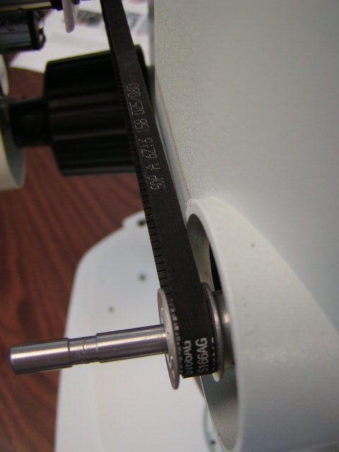
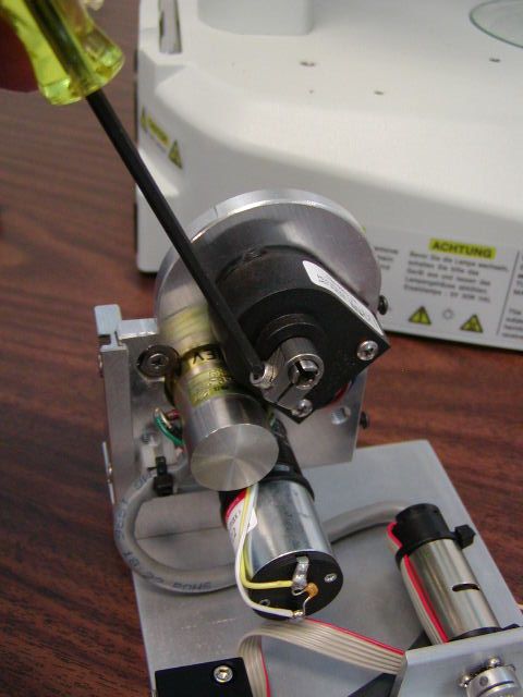
Install and tighten the zoom drive belt as outlined in figures 22 through 25
Part 6- Installing the motor drive cover plate & fine focus knob
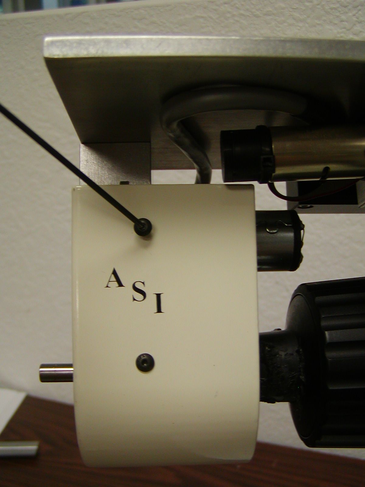
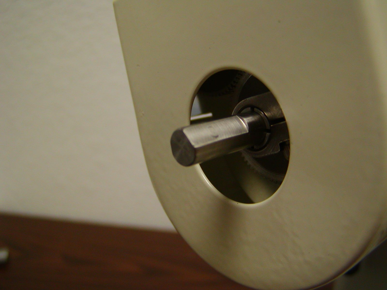
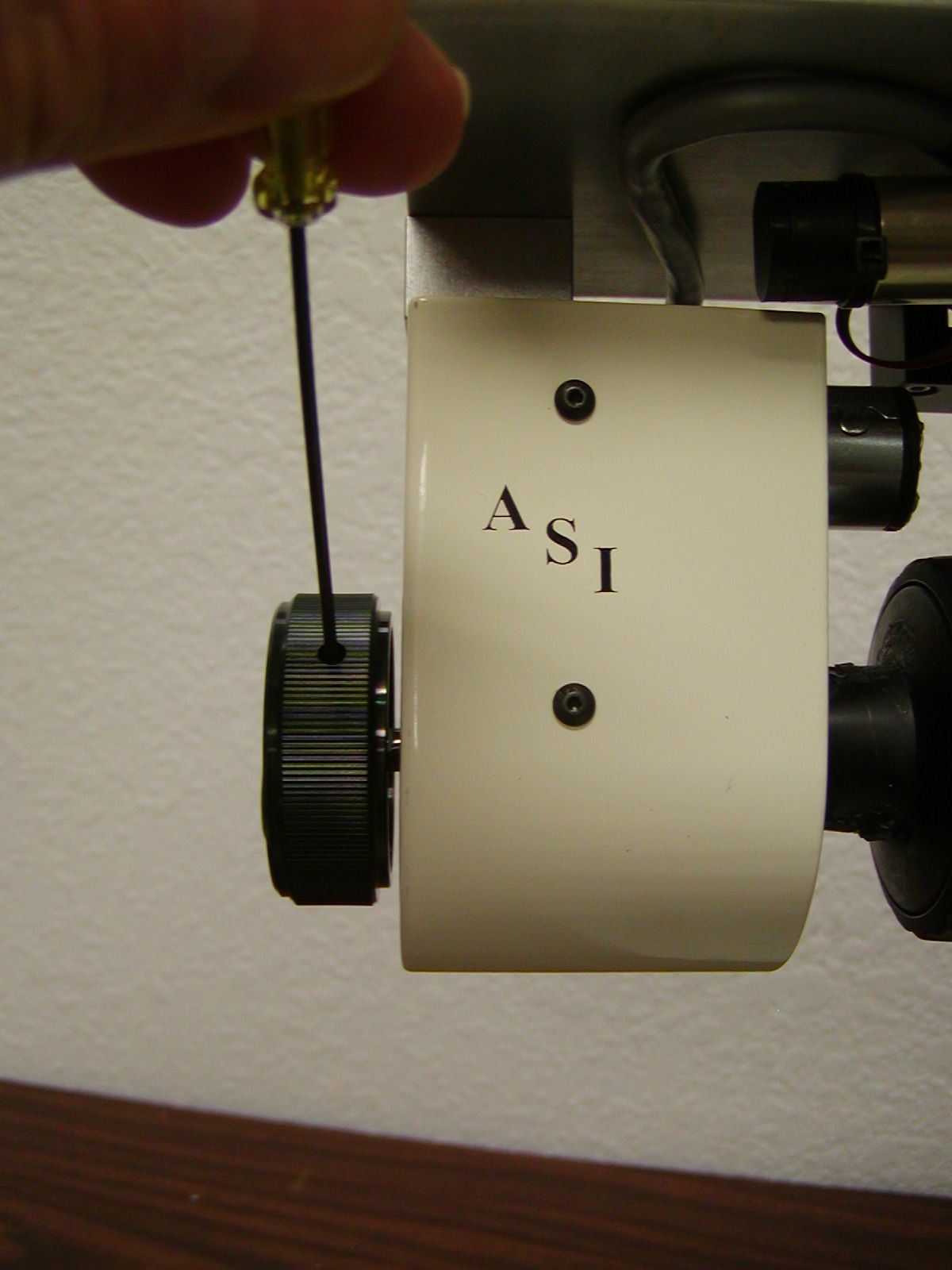
Install the drive cover and left focus knob as shown in figures 27 through 29.
Part 7 Connecting the cables to the controller
- Install the drive cable from the motor drive assembly to the controller connector labeled “”
- Install the dual foot switches to the controller connector labeled “ Foot Switches”
- Install the single foot switch to the BNC connector on the controller.
- Install the RS232 serial cable from the com port on your computer to the controller connector labeled “Serial In”
- Install the power connector & plug the power pack in to AC power.