Table of Contents
Olympus BX51WI Z-Drive Installation Procedure
The procedure below outlines the steps necessary to install the ASI Microscope Focus Controller Drive onto the Olympus BX51WI microscope.
To perform the following steps you will need the following tools:
Medium cross blade screwdriver 0.05, 1/16, 5/64 and 7/64 inch hex wrenches (ASI provides the hex wrenches.)
The procedure has four parts:
- Removing the drive belt cover, the left fine focus knob and installing the clutch plate
- Installing the baseplate & diffuser switch extender
- Installing and aligning the motor drive assembly
- Installing the motor drive cover plate and fine focus knob
Part 1 - Removing the drive belt cover, the left fine focus knob and installing the clutch plate
Remove the drive belt cover & left fine focus knob from the microscope as follows:
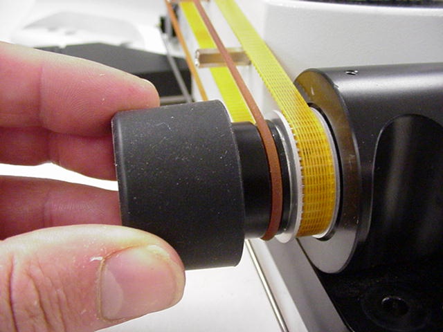
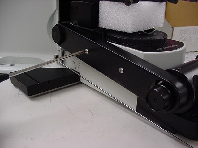
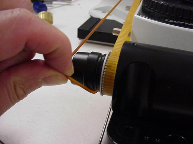
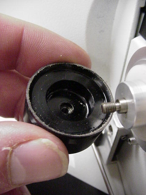
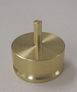
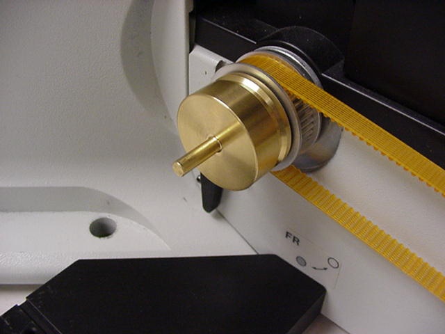
As outlined in figures 1 through 6 on the proceeding page remove the original focus drive knobs, belt drive cover & belt drive. Install the brass ASI clutch assembly in place of the knob removed in figure 4. After installing the brass ASI clutch assembly, as shown in figure 6, replace the drive belt that was removed in figure 3. After the belt has been installed the belt cover that was removed in figure 2 can be reinstalled.
Part 2 - Installing the Baseplate& diffuser switch extender
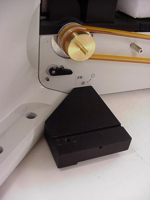
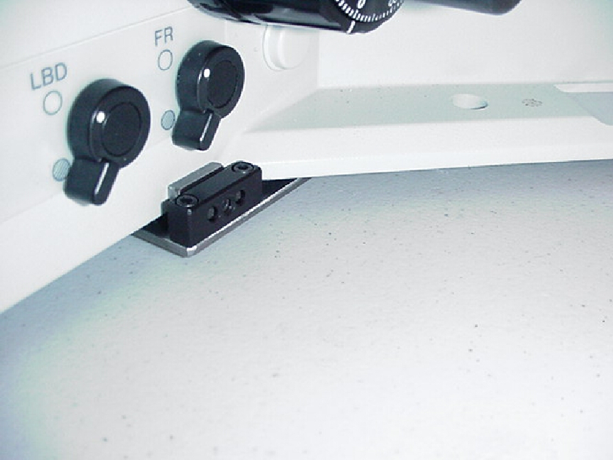
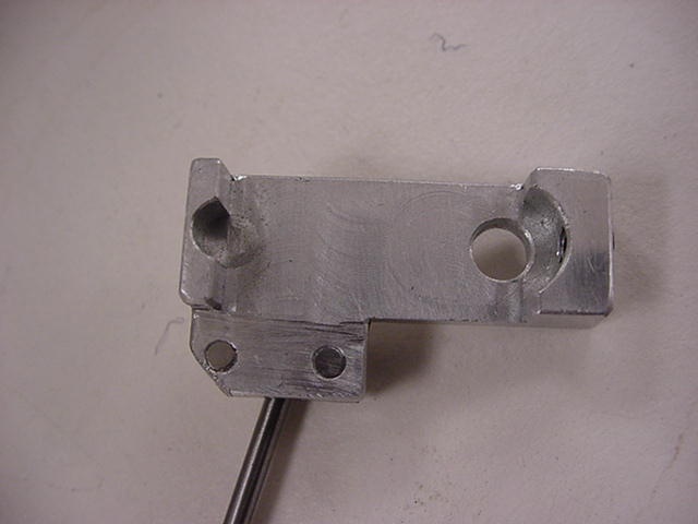
Locate the baseplate and remove the ASI drive from it (if it is attached) by using the 7/64” Allen wrench to remove the horizontal adjustment screw. Position the base plate assembly it so that the baseplate on the left side of the microscope. Lift the front of the microscope up and slide the base plate under the microscope so that angled portion of the base plate is aligned with the contour of the microscope as shown in figure 7. Hold the baseplate against the bottom of the microscope as shown in figure 8, and secure the baseplate in place by tightening the setcrew clamp shown in figure 9.
Installing the diffuser switch extender
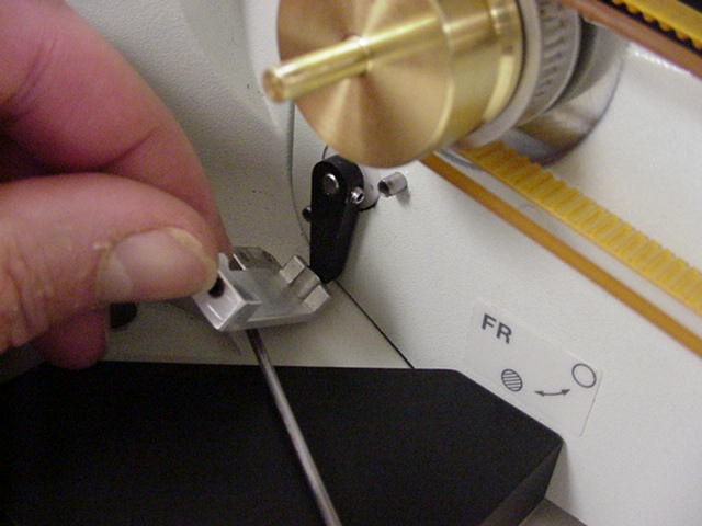
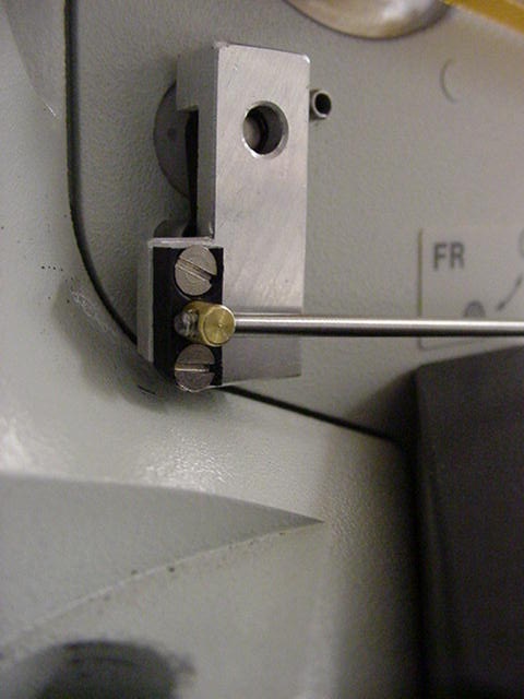
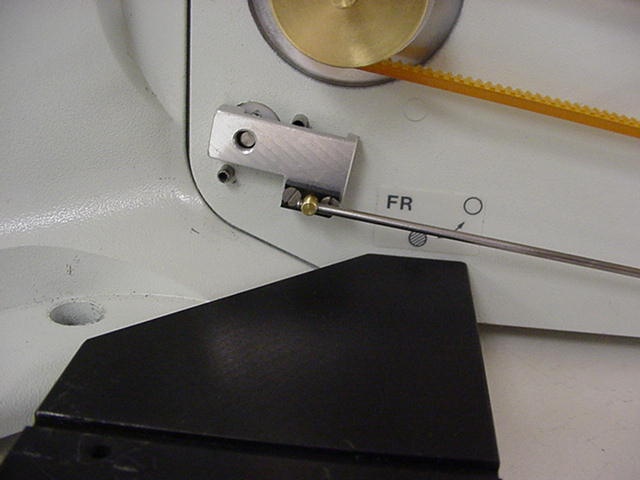
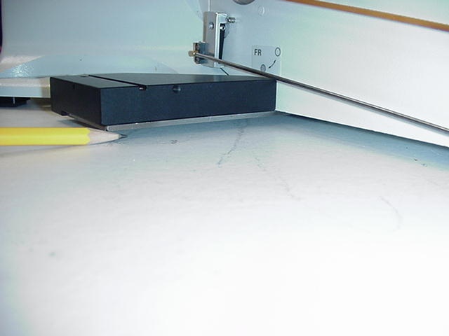
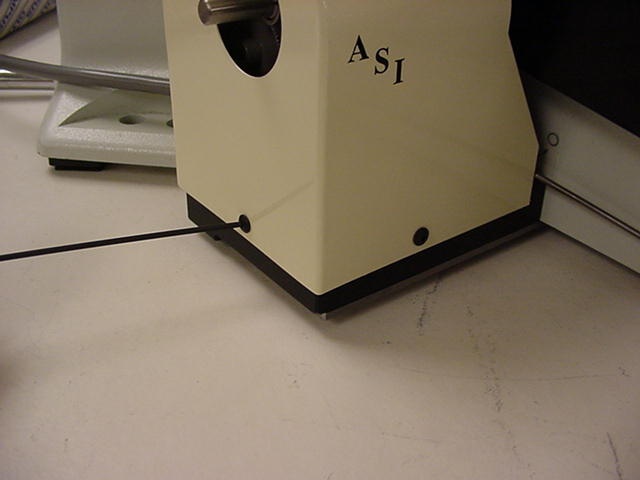
Locate the diffuser switch extender as shown in figure 10, and install it as shown in figure 11. The diffuser switch extender allows the diffuser switch to be accessed via the rod that extends out the front as shown in figure 13. Pushing the rod in will place the switch in the position shown in figure 12, and pulling the rod out will place the switch in the position shown in figure 13.
Part 3 - Installing and Aligning the Motor Drive
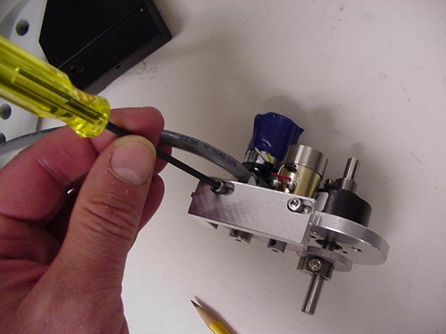
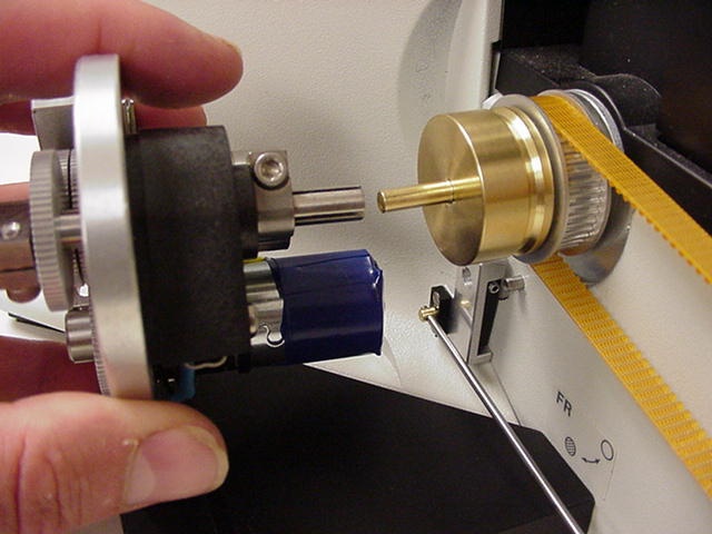
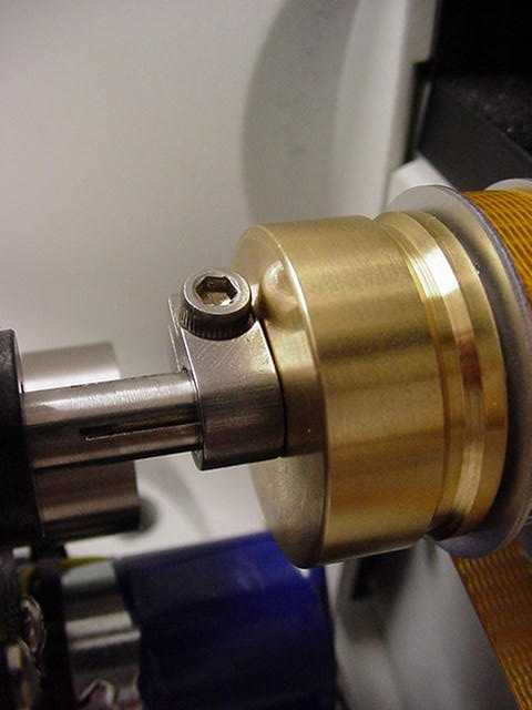
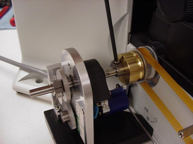
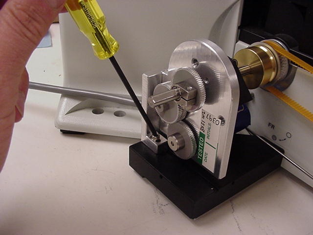
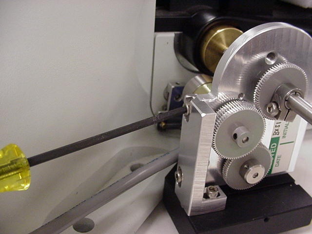
Locate the ASI fine focus motor drive, vertical adjustment bar, and vertical adjustment screw (M4 x 12 hex screw). Use the 7/64” Allen wrench to loosen the two vertical adjustment screws located on the vertical adjustment bar as shown in figure14. Align the drive shaft on the ASI drive with the microscope fine focus shaft, as shown in figure 15, and slide the motor drive over the fine focus shaft.
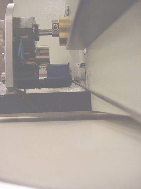
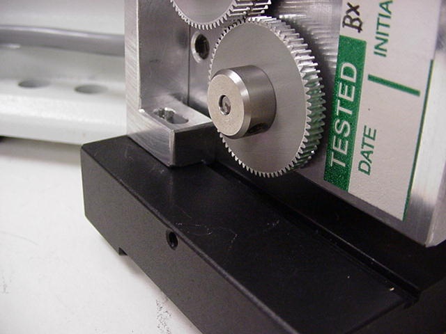
Rotate the drive plate and vertical adjustment bar assembly so that the tab that is on the bottom of the vertical adjustment bar slides into the machined groove on the base plate as shown in figure 16.
Press the clamp against the brass clutch plate as shown in figure 17, and use the 7/64-inch hex wrench to tighten the drive shaft clamp as shown in figure 18.
Use the 7/64” Allen wrench to screw in the horizontal adjustment screw but leave it loose enough so that the vertical adjustment bar assembly can slide within the groove.
Slide the motor drive up and down, forward and backward slightly while turning the right fine focus knob until it is in the position where minimum drag is felt on the right focus knob. Secure the motor drive into position by tightening the horizontal and vertical adjustment screws.
Recheck the alignment by noting the drag on the right fine focus knob. No noticeable drag should be felt. Repeat the steps above, if necessary.
Part 4 - Installing the Motor Drive Cover Plate and Fine Focus Knob
Locate the motor drive cover. Remove the 4/40 button head screws from the drive with the 1/16” Allen wrench. Position the motor drive cover over the motor drive assembly and secure in place using the 4/40 button head screws.
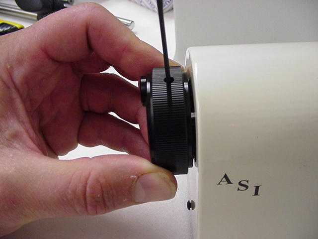
Slide the new black microscope fine focus knob over the shaft extension and press it on all the way. Use the 1/16” Allen wrench to tighten the setscrews to secure the knob on the shaft.
This completes the procedure for installing the ASI Microscope Focus Controller Drive onto the Olympus BX51 Microscope.