Table of Contents
Olympus BH-2 Microscope Motor Drive Installation
Motor Drive Installation
This procedure steps you through the installation and alignment of the ASI motor drive onto the Olympus BH-2 microscope. The following tools are required for this procedure:
Small knife or screwdriver
2.5 mm Allen wrench ( Provided )
3.0 mm Allen wrench ( Provided )
1.5 mm Allen wrench ( Provided )
3/32 mm Allen wrench ( Provided )
5/64 mm Allen wrench ( Provided )
7/64 mm Allen wrench ( Provided )
9/64 mm Allen wrench ( Provided )
1/16 mm Allen wrench ( Provided )
Preparing The Microscope
In this part of the procedure the left fine focus knob will be removed from the microscope:
Prior to removing left fine focus knob, the microscope stage should be fully lowered. To do this, release the lock by rotating fully counter-clockwise the lock ring behind the left coarse focus knob, then rotate the coarse knob to lower the stage all the way down.
Note: the terms left and right refer to the sides of the microscope as viewed from the front.
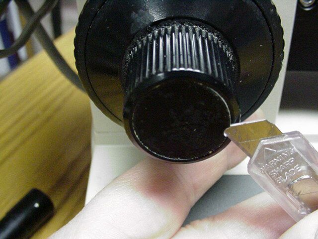
1) Carefully slip the knife point into the inside edge of the left fine focus knob end and pry out the 20mm black disk that covers the fine focus knob attachment screw.
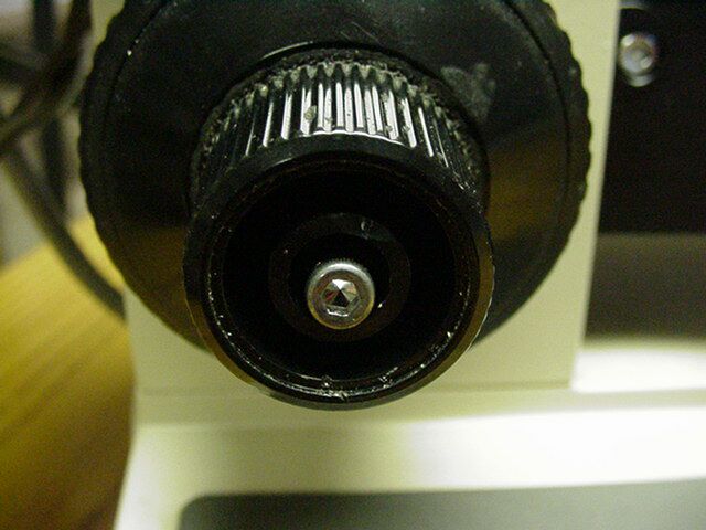
2) Remove the left fine focus knob by first removing the attachment screw using the 2.5mm hex wrench then pulling the knob off of the fine focus shaft. It will be necessary to hold the right fine focus knob while removing the screw to prevent the shaft from turning.
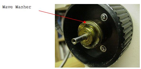
3) After the knob has been removed insure that the wave washer is still located on the brass clutch assembly on the focus shaft. If the washer has stuck to the fine focus knob that was removed place it as shown on to the focus shaft.
Installing the Drive and Back plate assembly
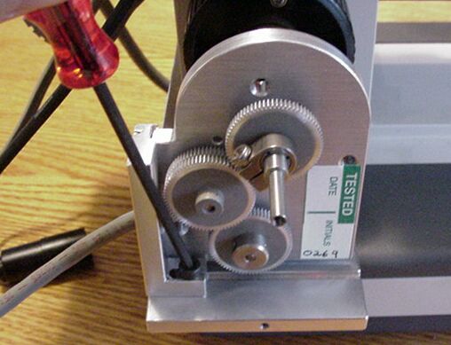
Locate the motor drive, the back plate and the brass clutch plate.
In this step we will install the ASI backplate and motor drive assembly as a unit. The ASI backplate will be installed and clamped to the back of the microscope as shown only after the motor drive is clamped onto the fine focus shaft of the microscope. Before installing the backplate and drive assembly loosen but do not remove the horizontal and vertical adjustment screws. When these screws are loosened the motor drive should move freely about in the horizontal and vertical adjustment axis.
Alternatively the drive and the back plate can be installed separately. In this installation the drive is removed from the back plate by removing the horizontal adjustment screw.
Installing the Drive & Brass Clutch Plate
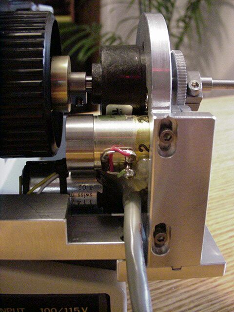
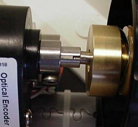
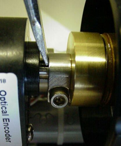
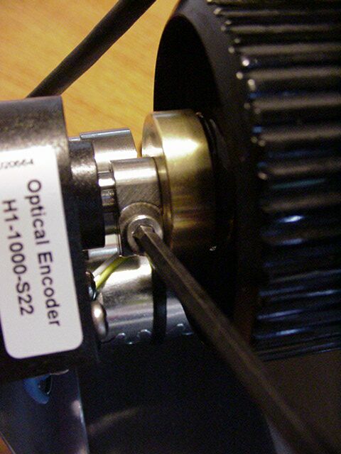
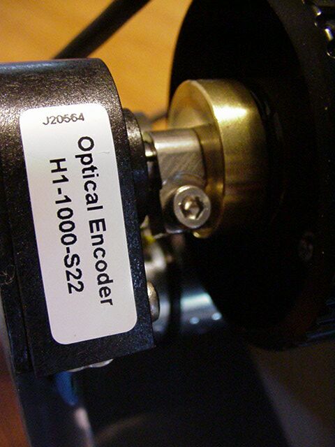
Use the 7/64 Allen wrench to loosen the clamp that is located on the ASI drive shaft. This clamp is located at the end of the drive shaft as it protrudes out of the black encoder cover. Once the clamp is loose slide it back towards the encoder and slide the brass clutch plate onto the ASI drive shaft. The clutch plate should slide onto the drive shaft with the milled out portion pointing away from the encoder. While holding the right fine focus knob slide the motor drive and back plate assembly in towards the microscope, when the ASI drive shaft is close enough, position the hollow end of the drive shaft (protruding from the black encoder) over the fine focus shaft on the microscope. Orient the motor assembly so that the two shafts are aligned, and then push the motor assembly onto the microscope. If you do not hold the right fine focus knob the microscope’s fine focus shaft may be pressed over towards the right of the microscope. If this happens simply push the right fine focus knob in towards the microscope to push the shaft back.
Press the drive onto the microscope until the side of the back plate assembly slides against the side of the microscope, or if installing the drive and back plate separately: push the drive on until the tab on the adjustment bar seats into the grove on the back plate. While holding the drive in place with one hand use a screw driver to press the clamp against the brass clutch plate and press the brass plate against the wave washer and focus shaft. Hold this in place and use the 7/64 inch hex wrench to securely tighten the clamp. Note The Clamp Must Be Securely Tightened or the drive and clutch may slip.
Aligning the drive
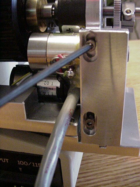
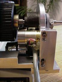
After installing & securing the drive and brass clutch plate to the focus shaft of the microscope the back plate can be positioned and secured. Position the back plate to a point midway along the slots for the two vertical adjustment screws and secure it in place by tightening the set screw to depress the clamp on side of the microscope.
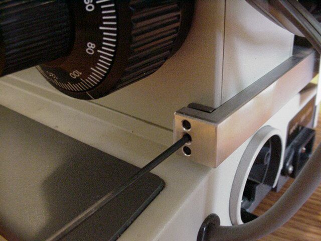 Use the 5/64” Allen Wrench to tighten the Base plate clamp at a point where the vertical adjustment screws are midway in the slots
After securing the back plate check for proper drive alignment be rotating the right fine focus knob. The drive is usually self aligning and when properly aligned no drag is felt, other then that caused by the gears, while rotating the fine focus knob. When the dive is in a position of proper alignment use the 5/32 Allen wrench to tighten the horizontal, and vertical adjustment screws at the position where minimum drag is felt.
Recheck for minimum drag on the fine focus shaft by turning the right fine focus knob. If there is any drag felt at any particular point while rotating the right fine focus knob repeat the alignment procedure by loosening the horizontal, and vertical adjustment screws and repositioning the drive. The drive is usually self aligning , and if realignment is necessary loosen the horizontal, and z vertical adjustment screws and move the drive so that is slides into its natural position and then tighten the two adjustment screws with the 5/32 allen wrench.
Step 6 - Installing the cover & left fine focus knob
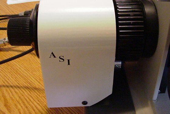
Remove the two screws from the edges of the drive assembly. Locate the ASI cover plate. Place it in position over the motor drive assembly and secure it with the screws just removed. Place the left fine focus knob over the protruding end of the drive shaft and secure it in place with the original screw using the 2.5 mm allen wrench. Install the 20mm black disk that covers the fine focus knob attachment screw. This 20mm black disk was removed in step #1.
Connecting the motor drive to the controller and computer
Please refer to the wiring drawings and diagrams given in the manual
Tools Needed: Small slotted screw driver.
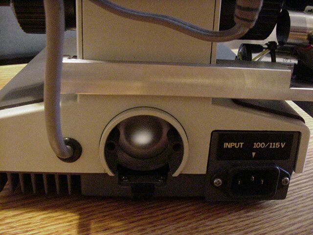
1) Locate the drive cable. Connect one end of the drive cable to the pigtail extending from the motor drive near the microscope and the other end to mating connector on the back of the Microscope Focus Controller, or MS-2000 unit labeled “Drive”. Secure the cable to the drive by tightening the screws at each end of the connector.
2) Locate the computer interconnect cable. Connect one end to the mating connector on the back of the controller labeled “Serial In”. Connect the other end to the appropriate serial output connector on your computer. .
3) Plug in the power cord / power supply
This completes the steps necessary to interconnect the ASI motor drive, focus controller and computer. Please refer to the operation section of this manual before using the unit