Table of Contents
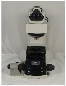
Nikon Eclipse Ni - ASI Z-Axis Motor Drive Installation
This procedure steps you through the installation and alignment of the ASI Z-axis motor drive onto the Nikon Eclipse Ni microscope.
The following tools are required for this procedure:
-Small Flathead Screwdriver
- 1.5 mm hex wrench
- 2 mm hex wrench
- 3 mm hex wrench
The procedure has six parts:
1.) Removing the left fine focus knob
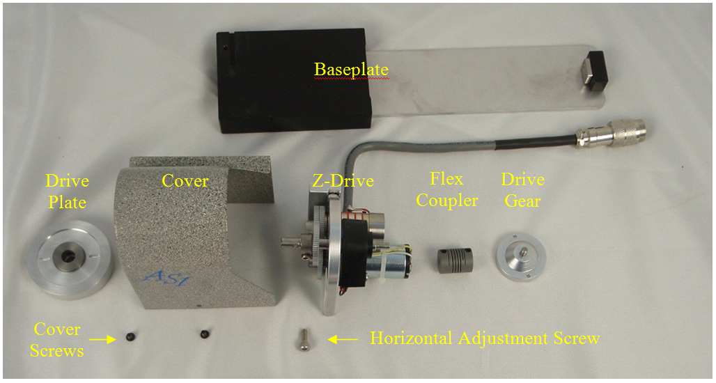
2.) Installing the Drive Gear
3.) Installing flexible coupling
4.) Installing and aligning the motor drive assembly and baseplate.
5.) Installing the cover, Drive Plate, and left fine focus knob.
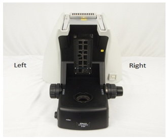
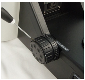
Part 1: Removing the Left Fine Focus Knob
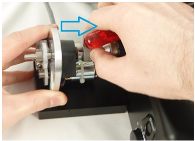
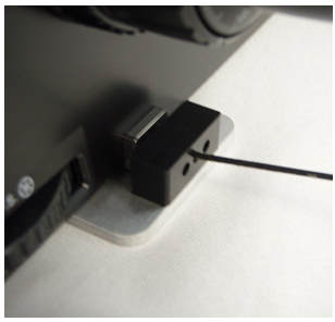
1. Using a flathead screwdriver, carefully pry off the fine focus knob off the Left side of the microscope. The knob is held on by a magnetic clamp which should release with a little amount of pressure.
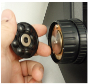
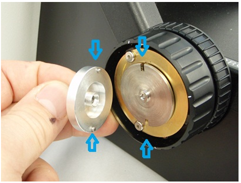
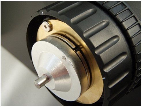
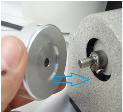
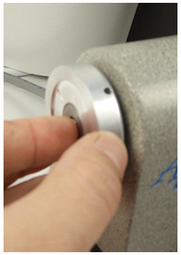
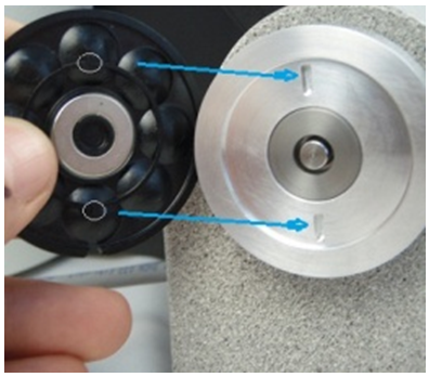
Part 2: Installing the Drive Gear
1. Find the drive gear. 2. Align the posts on the Drive Gear with the slots on the microscopes fine focus drive plate. 3. Slide the Drive Gear on to the microscopes fine focus drive plate so that the gear posts engage the slosts on the plate. Note: The drive gear will magnetically lock onto the plate. In some cases the microscopes find focus drive plate will be slightly warped preventing a flat fit – the flex coupler will compensate for this.
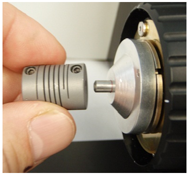
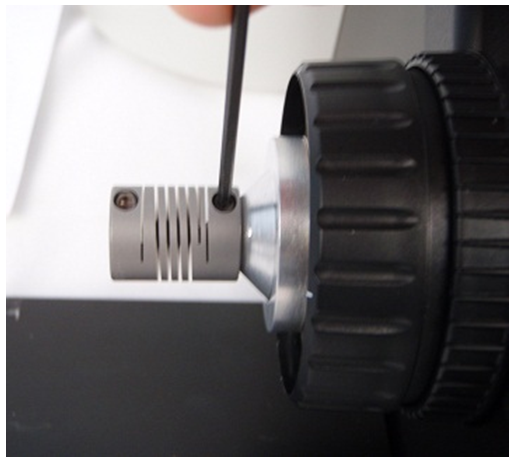
Part-3: Installing Flexible Coupling.
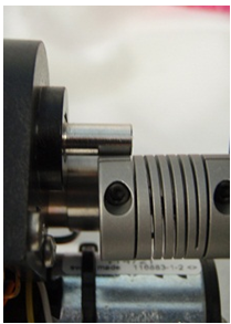
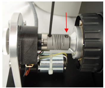
1. While holding the right hand knob in place, press the coupler on firmly so that the coupler is all the way on. Ensure that it is pressed against the Drive Gear without pushing the right focus knob out on the other side.
2. Lightly tighten the clamp on the microscope end with a 2 mm hex wrench. Note: It may be neccissary to slide the flex coupler back and forth to ensure proper alignment, so only lightly tighten the flex coupler at this point.
3. Ensure the Drive Gear is still firmly locked to the microscope.
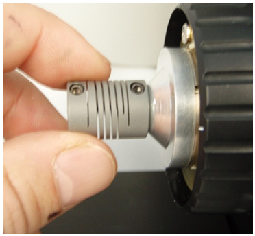
Ensuring the coupler is all the way on the Drive Gear shaft, lightly tighten the flex coupler set screw.
You may have to loosen this screw later to slide the flex coupler back and forth to ensure proper alignment of the Z-Drive post with the Drive Gear post.
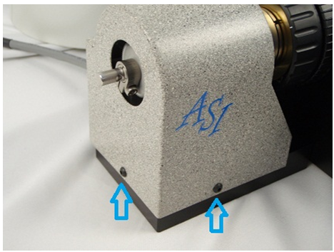
Part-4: Installing and Aligning the Z-axis Motor Drive and Baseplate
1. If shipped assembled, use the 3 mm hex wrench and disassemble the Z-drive motor assembly from base plate by removing the horizontal adjustment screw. At this time, also loosen the two vertical adjustment screws.
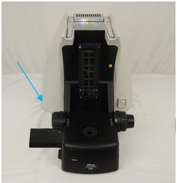
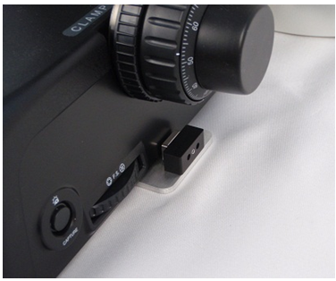
2. Slide the baseplate assembly completely under the microscope as shown until the small stop plate located on the baseplate is completely against the side of the microscope. This stop plate should be parallel with the bottom of the microscope. Align the plate beneath the focus knobs.
3. Leave base plate clamp slightly loose for later adjustment. 4. Slide the drive shaft of the motor drive assembly into the flexible coupler.
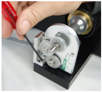
5. Rotate the adjustment bar so that the lip on the bottom of the adjustment bar mates with the groove in the baseplate. Align the holes on the adjustment bar to those on the drive and the baseplate, and screw in the horizontal adjustment screw to hold the drive assembly in place using the 3mm hex wrench. Leave the adjustment screws loose enough so that later the drive can slide up and down and the adjustment bar can slide back and forth within the baseplate.
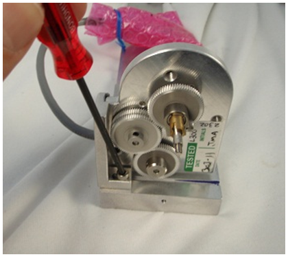
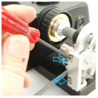
6. After verifying the baseplate and motor drive is appropriately positioned under the microscope, snugly tighten the baseplate clamp on the right side of the microscope. Use the 1.5mm hex wrench to tighten the setscrew located in the middle of the clamp assembly as shown. Tightening this setscrew will cause the silver bar to press against the side of the microscope. Ensure that the setscrew is securely tightened to hold the baseplate assembly in place.
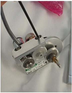
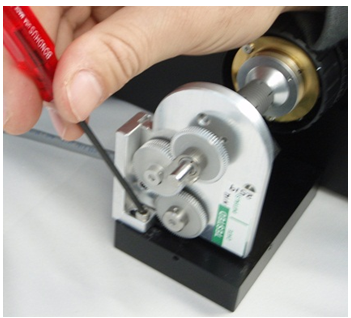
7. Tighten the clamp of the flexible coupler onto the drive shaft of the Z-drive unit using the 2mm hex wrench. Note: The flexible coupler clamp must be securely tightened or the drive may slip. 8. Lightly tighten the vertical and horizontal adjustment screws as shown. Since the motor is usually self-aligning, this should be a good position for the drive. Check the alignment by noting the drag while rotating the right-hand fine focus knob. No noticeable drag should be felt for the full 360º rotation of the fine focus knob. If any drag is felt other than the slight drag of the gears, loosen the vertical and horizontal adjustment screws and move the drive to a point where no drag is felt. Then tighten the vertical and horizontal adjustment screws.
Note: there should be no point throughout the 360º rotation of the fine focus knob where an increase in drag is felt. If drag is felt, repeat the above steps. In some cases sliding the flex coupler back and forth between the drive shaft and the Drive Gear shaft will help determine if the two shafts are properly aligned – be sure to retighten the coupler set screws so there is no slippage!
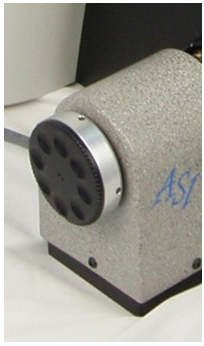
Part 5: Installing the Motor Drive Cover Plate and Fine Focus Knob
1. Locate the motor drive cover. Position it over the motor drive assembly and secure in place as shown, using the two small cover screws with the 2mm hex wrench provided. 2. Carfully slide the Drive Plate the Z-Drive shaft so that the drive plate is flush with the end of the Z-Drive shaft.
3. Tighten the two set screws on the side of the Drive Plate with a 1.5mm hex wrench.
4. Align the posts on the back of the microscope’s fine focus knob (removed from the microscope in part 1), with the slots on the drive plate.
5. Press the knob on till it magnetically locks onto the Drive Plate.
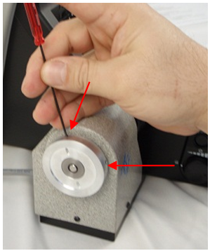
Align the posts on the original microscope knob the slots on the drive plate and press on. The knob should magnetically attach to the plate, completing the installation procedure.
This completes the procedure for installing the ASI Z-axis motor drive onto the Nikon EL200N.