Table of Contents
Nikon Diaphot 200/300 & TE200 /300 Z-Axis Drive Installation Procedure
The procedure below outlines the steps necessary to install the ASI Microscope Focus Controller Drive onto the Nikon Diaphot microscope.
To perform the following steps you will need the following tools:
Small flat blade screw driver 3mm, 5/64 and 7/64 inch hex wrenches ASI provides the hex wrenches.
The procedure has three parts:
- Removing the left fine focus knob
- Installing the baseplate
- Installing and aligning the motor drive assembly
- Installing the motor drive cover plate & fine focus knob
Part 1 - Removing the Left Fine Focus Knob & Brass Adapter plate
Remove the left fine focus knob from the microscope as follows:
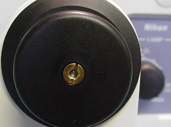
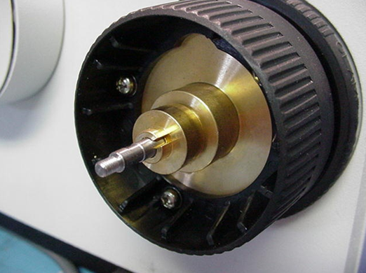
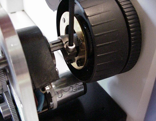
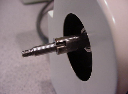
Pull off the rubber boot from the end of the left fine focus knob to expose the nut shown in figure 1. Use screwdriver to remove this nut. Pull knob straight off to expose brass adapter plate as shown in figure 2.
a) Use screwdriver to remove nut. Remove the fine focus knob by grasping it firmly and pulling it straight off.
Part 2 - Installing the Baseplate
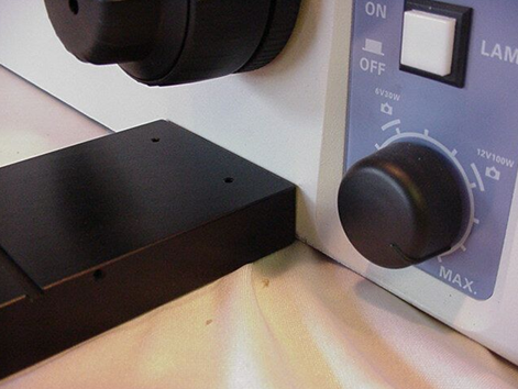
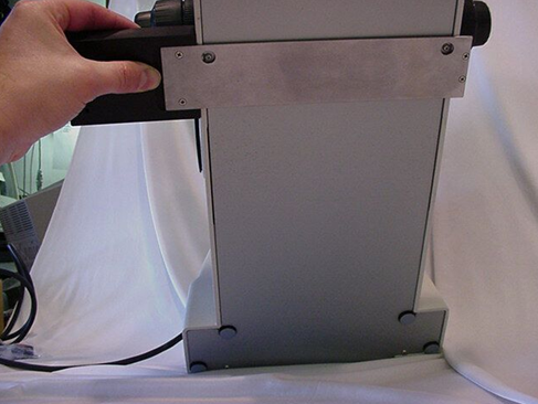
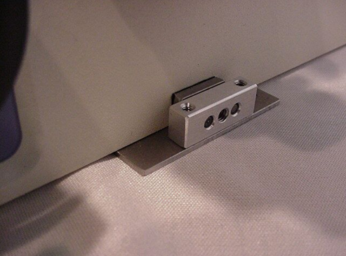
Locate the baseplate. If the motor drive is attached to the base plate use the 3mm Allen wrench to remove the horizontal adjustment screw to remove the drive from the base plate. Position the base plate so that the large baseplate is on the left side of the microscope. Lift the front of the microscope up and slide the baseplate under the microscope so that the horizontal adjustment bar is centered under the left focus knob as shown in figure # 3. There are two clearance holes, as shown in figure # 4, for two screws on the bottom of the microscope ( TE200 / 300 series ). When the baseplate is “about” in the correct position you will feel the screw drop into the holes. Leave the clamp shown in figure # 5 loose at this time.
Part-3 Installing & Aligning the Motor Drive
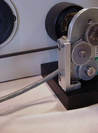
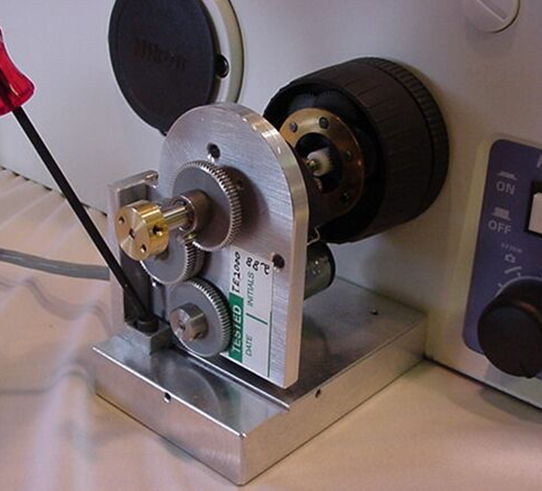
a) Loosen the two Vertical screws that secure the drive to the adjustment bar as shown in figure 6. Use the 7/64“hex wrench. Loosen the screws just enough so that the drive can slide easily in the groove in the adjustment bar.
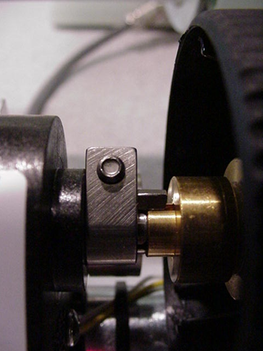
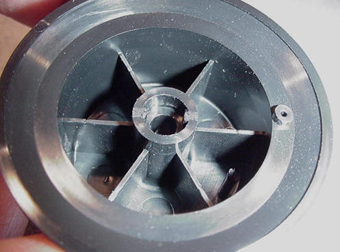
b) Locate the ASI fine focus motor drive and vertical adjustment screw (M4 x 12 hex head screw removed when the base plate was installed). Align the drive shaft on the ASI drive with the microscope fine focus shaft and slide the motor drive over the fine focus shaft as shown in figure 7. Insure that tab on the end of the clamp goes into the slot on the brass piece, or white gear. Hold the clamp firmly against on the brass piece, or white gear, and use the 7/64” Allen wrench to tighten the clamp as shown in figure 8.
c) Rotate the drive so that the tab on the bottom of the adjustment bar fits into the grove on the baseplate. Install, but do not completely tighten the vertical adjustment screw ( figure # 9 ) to hold the drive in place. Please Note the baseplate may need to be moved to properly align the adjustment bar.
d) Slide the motor drive up and down, forward and backward slightly while turning the right fine focus knob until it is in the position where minimum drag is felt on the right focus knob. Secure the motor drive into position by tightening the horizontal and vertical adjustment screws.

e) Use the 5/64” Allen wrench to tighten the base plate clamp set screw shown in figure # 10 to secure the base plate to the microscope
f) Recheck the alignment by noting the drag on the right fine focus knob. No noticeable drag should be felt at any point with in the full 360 degrees of rotation. If any noticeable drag is felt loosen the Vertical & Horizontal adjustment screw and repeat the step d above if necessary.
Part 4-Installing the motor drive cover plate & fine focus knob.

a) Locate the motor drive cover. Remove the 4/40 button head screws from the base plate with the 1/16 “ Allen wrench. Position the motor drive covert over the motor drive assembly and secure in place using the 4/40 button head screws as shown in figure # 11.

The tabs on the original focus knob fit into the slots on the ASI shaft & the knob is secured in place with the original nut.