Table of Contents
Detailed Pictorial MS-2000 Cable Connection Instructions
This procedure gives pictorial instructions on how to connect nearly all of the cables to your MS-2000 controller. (The USB and Serial-Out cables are not covered here.) Please note that, depending upon what options you have selected when purchasing your unit, some of the connections mentioned may not be available on the unit that you received.

MS2000 and RM2000 Case Variations


Connecting XY Stage Cables: Figures 2 through 8:


Connecting XY Stage Linear encoders: Figures 9 through 18


Connecting Z-Axis Drive: Figure 14 though 16


Connecting Z-Axis Linear Encoder: Figure 17 through 18


Connecting RS232 Serial Cable: Figure 19 through 22


Connecting Power: Figure 23 through 24

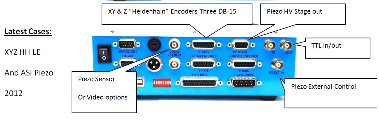
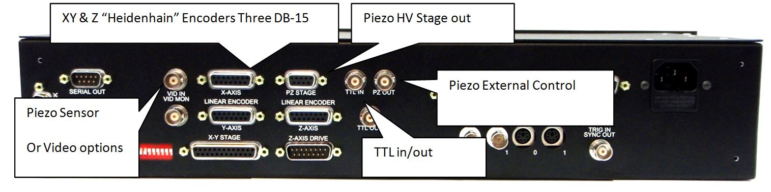
Connecting Piezo Stage to MS2000 controller
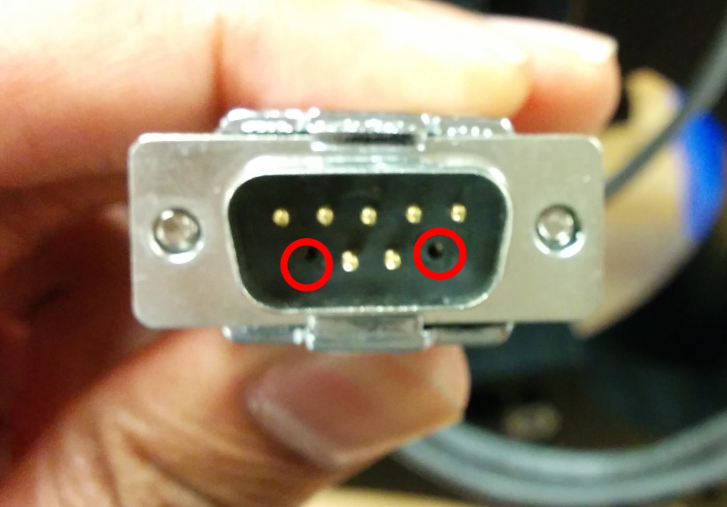
The Piezo stage connector is a male DB9 connector with 2 pins removed.
The Corresponding connector on the controller is a Female DB9 connector with two pins permanently plugged. This prevents connecting serial cable or crisp accidently to the piezo connector, Doing so will damage these devices as the Piezo connector carries very high voltage.

Apart from the DB9, the controller also has 2 BNC connector PZ Sensor Out and EXT IN . These are optional connectors and don't need to be connected for regular operation.

Connecting Piezo and TTL BNCs:Figure 25 through 26


Connecting to LED Illuminator when 4-Pin Connector is Present

The LED illuminator connects to the MS2000, MFC2000, RM2000 and TG-1000 with the cable shown below.

The Cable has a mini-usb end that plugs into the Illuminator itself. Then the 4-Pin HiRose connector plugs into the Controller. Location of the HIRose connector is shown below.


Connecting to LED Illuminator when 4-Pin Connector is Absent
However not all controllers come with the 4-Pin HiRose connector installed.

In that case, ASI will supply this Y cable(shown below). The HiRose end plugs into the LED cable's HiRose end. Then the BNC plugs into the TTL Out , and the wall-wart to the wall wart.


Please note , the controller needs a LED firmware module to operate the LED. If the LED illuminator was ordered later as an upgrade , controller may not have the necessary firmware. To Check , Issue serial command BU X . If the controller replies with LED DIMMER then the controller has the necessary firmware needed. If not, contact ASI with your controller's serial number and request for it.