Table of Contents
MPPI-3 Pressure Injector

Summary of Operation
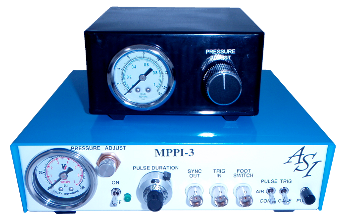
The Milli-Pulse Pressure Injector, Model MPPI-3, is a self-contained device for producing gas pressure pulses to an injection pipette. The unit offers linear control of both pressure and pulse duration.
The MPPI-3 provides three different means of initiating pressure pulses:
- a front panel push button
- an external 5 VDC TTL signal input
- an optional foot switch.
In addition to delivering a pulsed output, the MPPI-3 can also deliver continuous output or an output that is gated by an external TTL signal input.
The continuous output is useful for adjusting the rate of flow from the pipette tip prior to injecting and for clearing a clogged pipette. The gated output is useful for precisely controlling both pulse duration and repetition rate from an external source such as a stimulator or computer.
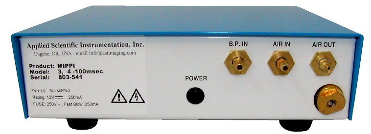
The MPPI-3 has an internal in-line air filter to exclude contaminants and guarantee the life of the solenoid valve. The filter protrudes from the rear panel for access to its moisture drain. The unit accepts a pressure source of up to 300 psi (2000 kPa) and has an output pressure range from 0 up to 100 psi (0 to 690 kPa).
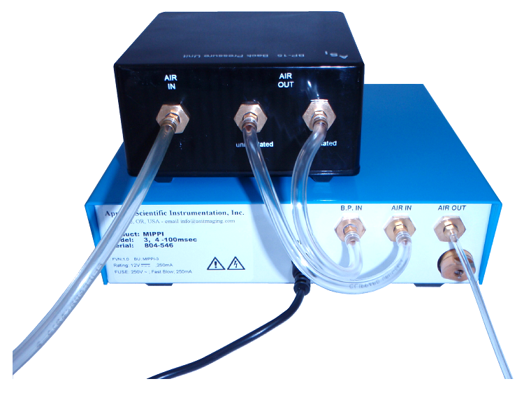
An optional back pressure module is available in instances where precise control of leakage from the pipette tip is required. This option compensates for any reverse flow in a pipette caused by capillary action by providing an adjustable (0-to-15 psi or 0-to-100 kPa) back pressure. If the back pressure input is not utilized, this port will act as an exhaust vent to spill the pressure between pulses. Optionally this port can be plugged to maintain some pressure between pulses.
Front Panel Connections
PRESSURE ADJUST Dial
This dial, in reference with the pressure gauge, sets the output pressure. The range of adjustment is 0 to 100 psi, dependent upon the available input pressure.
PULSE DURATION Dial
This 10-turn dial precisely sets of the duration of the pressure pulse. A locking lever on the dial can be activated to prevent the setting from being disturbed.
PULSE Push Button
This push button initiates the pressure pulse when the unit is in the Pulse mode of operation.
PULSED/CONTINUOUS Switch
This switch sets the mode of operation to either Pulsed or Continuous. In Pulsed mode, the unit delivers a precise pressure pulse in response to depressing the PULSE pushbutton, depressing the foot switch, or upon receipt of an external TTL input pulse. In Continuous mode, pressure will be continuously delivered.
TRIG/GATE Switch
This switch sets the modes of operation for the external TTL input signal. When in the TRIG position, a pressure pulse will occur each time the TTL signal makes a transition from approximately 0 volts to approximately +5 volts. The duration of the pulse is set by the front panel’s Pulse Duration dial. When the switch is in the GATE position, the pressure pulse will follow the external TTL input signal. That is, when the TTL signal is low (0 volts) no pressure will be delivered. When the TTL input is high (+5 volts), pressure will be delivered. This mode allows an external source such as a stimulator or signal generator to control both the repetition rate and the duration of pressure pulses.
SYNC OUT
Allows monitoring of the valve control (0 VDC = closed, +5 VDC = open) and the daisy-chaining of multiple controllers, as well as synchronizing the injection pulse with micromanipulators and piezo cell penetrators.
TRIG IN Connector
For external control, connect a TTL level signal to this BNC connector. The signal should switch between approximately 0 volts and approximately +5 volts. See TRIG/GATE switch above for the modes of control available via this input.
FOOT SWITCH Jack
Connect the optional foot switch to this jack for hands free operation of the MPPI-3. A pressure pulse will be delivered for each depression of the foot switch.
POWER Switch
This switch turns the MPPI-3 on and off. A pilot lamp indicates when it is on.
Rear Panel Connections
AIR IN Barbed Hose Fitting
Please refer to the drawing on page 4 for the air line connections.
AIR OUT Barbed Hose Fitting
Connect your injection pipette to this hose fitting.
B.P. INPUT
Connect the optional Back Pressure Unit (BPU) to this hose fitting. The optional BPU allows precise control of leakage from the pipette tip to compensate for any reverse flow in a pipette due to capillary action.
Note: The BPU unit is for micron size or smaller pipettes only.
Note: If the Back Pressure Unit (BPU) is used, then, between pulses, you will have back pressure at the pipette tip that is equal to the pressure setting on the BPU 0-to-15 psi (0-to-100 kPa).
Alternatively, leave this connection open or plug it. Leaving the port open allows the pressure between pulses to be vented to the ambient room pressure. Plugging the port allows some pressure to remain between pulses in instances where the preparation being injected has high hydrostatic pressure.
Pulse Duration Dial Setup
The pulse duration time delay setting for the MPPI-3 controller can be set with two internal jumpers. Following is the procedure for making these adjustments:
Warning! By opening the case, the internal circuits are exposed. The workbench, tools, and operator should be properly grounded to ensure protection from electrical static discharge (ESD). ESD can do permanent damage to the circuits on the board inside the controller. ESD damage from improper procedure is not covered by this product’s warranty.
Step 1:
Disconnect the power from the controller and move to an ESD safe work area.
Step 2:
Remove the six Phillips screws from the sides of the blue top cover.
Step 3:
Gently remove cover and set aside.
Step 4:
Locate jumper J5 on the back right corner of the circuit board.
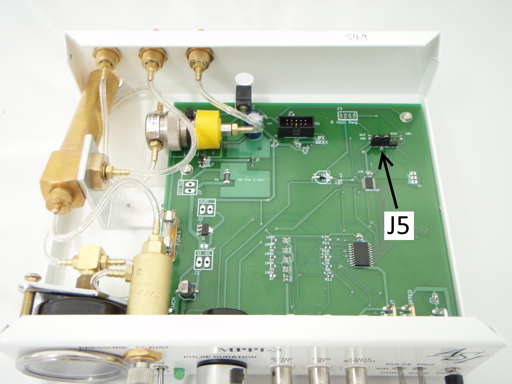
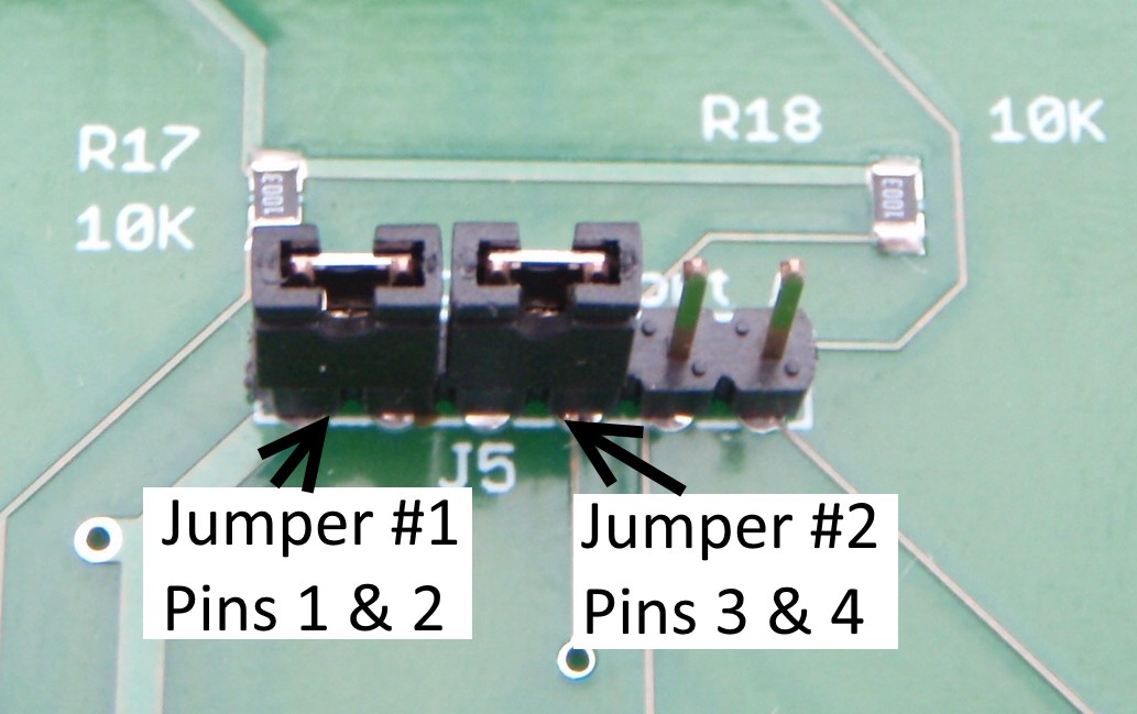
Note: While looking at the controller from the front, from left to right across J5, pins 1&2 are Jumper #1, and pins 3&4 are Jumper #2. The last two pins (the ones on the far right) are test pins and should never have jumpers attached to them.
Step 5:
Install or remove jumpers to pin combinations 1&2 and 3&4 using the following table to select the appropriate timing setting:
| Jumper #1 - Pins 1&2 | Jumper #2 - Pins 3&4 | Pulse Duration |
|---|---|---|
| Jumper | Jumper | 5 ms – 100 milliseconds |
| NO Jumper | Jumper | 5 ms – 1 second |
| Jumper | NO Jumper | 5 ms – 10 seconds |
| NO Jumper | NO Jumper | 5 ms – 60 seconds |
Note: ms = milliseconds
Step 6:
Replace blue cover and replace the six Phillips screws.
Maintenance
The MPPI-3 Milli Pulse Pressure Injector, has been designed and tested to provide years of reliable service.
Note: In order to insure that the unit operates as designed, use only nitrogen or clean dry compressed air as the pressure source.
The design of the MPPI-3 requires little maintenance on the part of the user. In fact, there are only two areas that the user needs to be aware. The first is to periodically check for moisture and other contaminants in the pressure source. The internal in-line filter that protrudes from the back of the unit has a small needle valve located on the bottom. This valve should be depressed periodically to check for moisture from the pressure source. If excessive moisture is noted, the pressure source should be changed. In the event that the filter becomes degraded or plugged, contact ASI for a replacement.
The second area of maintenance that the user should be aware is the replacement of the fuse. In the event that the MPPI-3 fails to turn on, the line fuse located inside the MPPI should be checked. If the fuse is blown, an exact replacement needs to be used. The MPPI-3 uses a 250mA fast-blow fuse. If the fuse blows again after replacement, please contact ASI for instructions on returning the unit for repair.
MPPI-3 Specifications
| Input Pressure Range | 0 to 100 psi (0 to 690 kPa) |
|---|---|
| Output Pressure Range | 0 to 100 psi (0 to 690 kPa) (dependent on input pressure) |
| Output Pulse Range | Four user-settable ranges: |
| 5 ms to 100 milliseconds | |
| 5 ms to 1 second | |
| 5 ms to 10 seconds | |
| 5 ms to 60 seconds | |
| Minimum duration is limited by the pneumatic solenoid valve to approximately 5 milliseconds | |
| Output Pulse Setting | Via a front panel calibrated 10-turn dial |
| Output Pulse Accuracy | 0.4% of full scale (crystal controlled) |
| Output Pulse Repeatability | 0.4% of full scale (1% over the life of the valve) |
| Output Pressure Gauge | Front panel analog gauge 0 to 100 psi (0 to 690 kPa) |
| Valve Life Expectancy | 100 million cycles |
| Modes of Operation | Continuous flow |
| Timed Pulse Duration flow control | |
| Gated flow control | |
| Control Options | Front panel push button switch |
| External TTL input signal | |
| Optional foot switch | |
| Output Sync | Allows monitoring of the valve control and the daisy-chaining of multiple controllers, as well as synchronizing the injection pulse with micromanipulators and piezo cell penetrators |
| Gas Input Fitting and Back Pressure Input Fitting | 1/8 inch barbed hose fitting |
| Gas Output Fitting | 1/16 inch barbed hose fitting |
| Recommended Gas | Nitrogen or clean dry compressed air (An internally-mounted input gas filter is provided) |
| Power Requirements | Power Module: 100 to 240 VAC, 50 to 60 Hz, 0.5A |
| Direct Power Connection: 12 VDC, 1.5A, 18 Watts | |
| Size | Unit Only: 2.7“ H x 8.2” W x 8.5“ D (69 x 209 x 216 mm) |
| Weight | Unit Only: 2.4 lb (1100 g) |
| Unit with Power Module & Cord: 3.2 lb (1450 g) | |
| BPU, Micropipette Holder, and Foot Switch: 1.5 lb (680 g) |
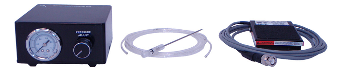
Optional Accessories
Micropipette Holder Option
Pipette holder. Can be mounted in a micromanipulator. Accepts standard 1 mm to 2 mm O.D. glass pipettes.
Foot Switch Option
Foot switch with 8-foot cord. Use for hands-free activation of pulses.
Back Pressure Unit Option
Back Pressure Unit (BPU). This small unit connects to the air line between the in-line filter and the MPPI-2, and attaches to the B.P. input port. It has an adjustable pressure regulator and pressure gauge. Use for precise adjustment of leakage from the pipette tip.
Note: The BPU unit is for micron size or smaller pipettes only.
Gas Filter Replacement
Replacement Gas Filter is available from ASI.
Warranty
Applied Scientific Instrumentation, Inc., hereafter referred to as ASI, guarantees this equipment against all defects in materials and workmanship to the original purchaser for a period of one (1) year from the date of shipment. ASI's responsibility to this warranty shall not arise until the buyer returns the defective product, freight prepaid, to ASI's facility. After the product is returned, ASI at its option, will replace or repair free of charge any defective component or device that it has manufactured. The warranty set forth above does not extend to damaged equipment resulting from alteration, misuse, negligence, abuse or as outlined below:
1. Equipment not manufactured by ASI that are offered as part of complete imaging systems carry the original equipment manufacturer's warranty.
THE WARRANTY AND REMEDIES SET FORTH ABOVE ARE IN LIEU OF ALL OTHER WARRANTIES. APPLIED SCIENTIFIC INSTRUMENTATION, INC. EXPRESSLY DISCLAIMS ALL OTHER WARRANTIES WHETHER EXPRESSED, IMPLIED OR STATUTORY, INCLUDING THE WARRANTIES OF MERCHANTABILITY AND FITNESS FOR A PARTICULAR PURPOSE AND AGAINST INFRINGEMENT.
In no event will ASI be liable for incidental or consequential damages, even if ASI has been advised of the possibility of such damages howsoever, arising out of the sale or use of the products described herein.