Table of Contents
MicroMirror Drive Card User Guide
The MicroMirror Drive card is a module for the TG-1000 system. Using this card user can control X and Y axes of 2 MEMS MicroMirrors. The card can be operated in external input mode (0 to 5V analog signal) or in internal input mode (thru onboard DAC so the mirror can be positioned thru serial commands and built in routines).
Although MEMS Mirrors are operated in open loop mode, a 5th order tunable Bessel filter is provided which can be used to avoid exciting the mechanical resonance of the MEMS mirrors.
Note: MEMS MicroMirrors are very sensitive to ESD, please observe precautions when handling this equipment. Even more than usual, it is important to never connect or disconnect the cables when system power is on.
Equipment and connectors
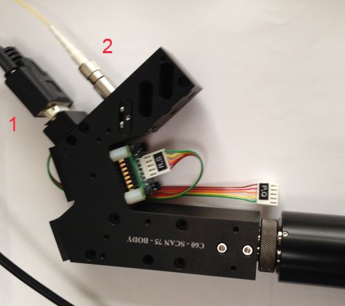
MicroMirror scanner body. The DB9 connector (1) connects to the MicroMirror Drive Card thru a DB9 straight cable. 2 is the fiber optic coupler. As shown in the picture, MicroMirror is connected to drive card as R and S axis. Newer scanners have the fiber connector on the end of the scanner body.
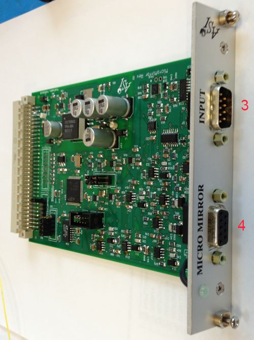
MicroMirror Drive Card. Connect 4 to MicroMirror Scanner body thru a DB9 straight cable. 3 is the input to accept analog signals. Analog input range is 0-5Volts.
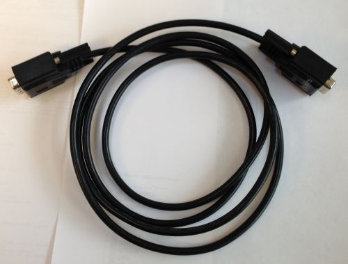
Straight DB9 cable to connect Driver card and scanner body.
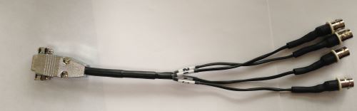
Use the connector to connect coax cables with user’s analog input to MicroMirror drive card. Coax connectors are marked 1,2,3,4. MicroMirror 1’s X , Y axis and MicroMirror 2’s X, Y axis respectively.
Electrical Characteristics of MicroMirror Drive Card
- Output Voltage : 0 to 130V
- Output Current: <1mA (100kOhm source resistance)
- Analog Input range: 0-5V
- Analog input amplification: x20
MEMS MicroMirror Details (most usual version)
- 1200um dia mirror
- Max angle x and y: 4.6 degrees
- Max voltage x and y axis: 131V
- Resonant frequency x and y axis ~2.5kHz
- Quality factor: 50
- Recommended LPF cutoff frequency, 6th order Bessel: 1KHz
- Further details can be found here: http://tinyurl.com/1200ummirror
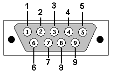
Connector Pinout
Output to Micromirror DB9 Female
| DB9 Pin | Description |
|---|---|
| 1 | Channel A (fast axis) positive, 0 to 130V out |
| 2 | Channel C (fast axis) positive, 0 to 130V out |
| 3 | Channel B (slow axis) positive, 0 to 130V out |
| 4 | Channel D (slow axis) positive, 0 to 130V out |
| 5 | Ground |
| 6 | Channel A (fast axis) negative, 130V to 0V out |
| 7 | Channel C (fast axis) negative, 130V to 0V out |
| 8 | Channel B (slow axis) negative, 130V to 0V out |
| 9 | Channel D (slow axis) negative, 130V to 0V out |
| Shielding | Ground |
DAC input to card DB9 Male
| DB9 Pin | Description |
|---|---|
| 1 | DAC input for Channel A, 5V max |
| 2 | DAC input for Channel C, 5V max |
| 3 | DAC input for Channel B, 5V max |
| 4 | DAC input for Channel D, 5V max |
| 5 | not connected |
| 6 | Ground |
| 7 | Ground |
| 8 | Ground |
| 9 | Ground |
| Shielding | Ground |
Shortcomings of the Drive Card
No calibration has been performed to make sure the relationship between the applied input voltage (in external input mode) or between the axis positions (in internal input mode) are accurate. However we can make a rough guess based on the micro-mirror specifications of 9.2degrees for 131V; with analog multiplication of 20x we expect each volt of analog input (in external mode) to move the mirror by approximately \begin{equation} \frac{20V}{131V}×9.2º = 1.4º\end{equation}. We expect the user to cross-calibrate the move amount with a corresponding stage movement. Before firmware v3.14 the DACK command could be used to set a scale factor for calibration, but starting with v3.14 it is assumed that the user will instead adjust the move position or single-axis amplitude accordingly.
Until and including version C of the Drive Card, the high-voltage amplifiers get very hot due to their quiescent current. In later versions of the card this issue is addressed by changing amplifier ICs. Occasionally cards (version C and before) fail due to overheating, so it is advised to turn of the TG-1000 controller when not in use. Contact ASI for assistance if the MicroMirror Drive Card appears to fail entirely (all the output pins on the DB9 connector to the Scanner will be 0V in that case).
MicroMirror-specific Serial Commands
Control of the MEMS MicroMirrors is similar to any other axis of the TG-1000 system. This means all the regular axis commands work (e.g. MOVE, MOVREL, WHERE, ZERO, INFO, etc.). The axis units are 1/1000 of a degree. So MOVE R=2000 moves the beam by about 2 degrees.
Apart from the regular axis commands here are some MicroMirror-related commands, including some that are “recycled” for a different use than for motor axes.
| 2016/03/14 18:19 | |
| 2016/03/14 20:27 | |
| 2016/03/15 19:46 | |
| 2016/03/17 19:27 | |
| 2016/03/17 19:41 | |
| 2016/03/17 19:33 | |
| 2016/02/22 19:30 | |
| 2016/03/16 20:04 |
Setting Filter Frequency
The MEM MicroMirror is analogous to a spring-mass system, and like a spring mass system it has a tendency to ring. Below is the frequency response and step response of the 1200um MEMS mirror as provided by the manufacturer.
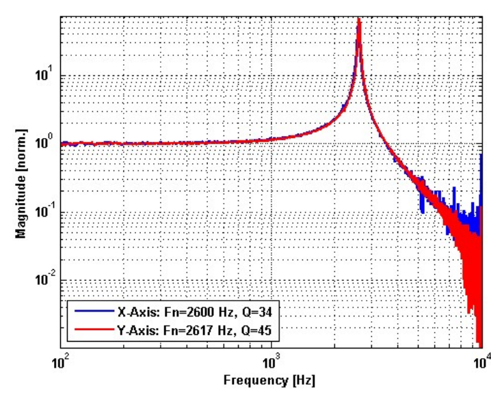
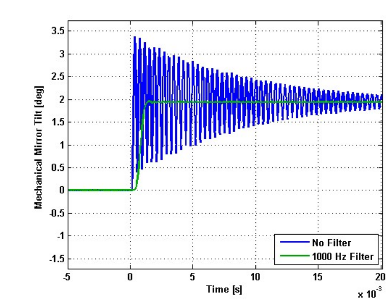
The MicroMirror card has a tunable Bessel filter to filter out resonating frequency elements from the input which helps reduce the mechanical ringing. The MEMS manufacturer recommends setting the filter frequency no more than 1/3 of the resonance frequency (about 850Hz), although based on ASI’s testing it is possible to go higher. The default filter frequency is 400Hz, and it may be changed using the BACKLASH command.
Multi-axis function
The multi-axis firmware module lets the MicroMirror Card generate patterns like circle and spiral. It is implemented but has not yet undergone extensive testing. It can also be used for XY stages if the firmware module is present.
| 2016/03/16 14:36 |
Single-axis functions
The single-axis firmware module lets the MicroMirror card generate patterns including ramps, triangles and pulses. This module is intended to run off a 4Khz internal clock, though provision has been made to accept an external clock on the TTL input (only lightly tested). They can also be configured to output TTL pulses upon completion of each cycle. For both these TTL functions, the corresponding physical connectors need to be in place.
Provision has been made for the user to control the following features of the single-axis output pattern:
- Peak-to-peak amplitude (SAA)
- Period (SAF)
- Pattern and miscellaneous configuration settings (SAP)
- Offset or initial center point (SAO)
Note that some of these settings are also used by the SPIM firmware module. When a SPIM scan is initiated then any active single-axis function on the MicroMirror card is stopped. When SPIM is armed for a piezo card any active single-axis function on the card is stopped.
The SAM command is used to activate and also inactivate single-axis patterns.
While a single-axis mode is active (i.e. when the pattern is being generated and output), the axis move status character (accessed by RDSTAT [axis]+) is set to A .
When single-axis mode is active then moving the axis (either using MOVE or MOVEREL or by using the joystick or wheels) will automatically update the offset. Thus, the single-axis pattern always has the same position on start-up as where it last was used, unless the SAO command has been used in the interim to select a new offset. However, moving the axis position while the single-axis mode is idle does not change the offset.
For MicroMirror cards with fast DACs (usually axes A and C, or axes P and Q), the single-axis functions update the fast DACs at a rate of 40kHz beginning with firmware version 2.8. Otherwise, the DAC update rate is 4kHz divided by the number of card axes. e.g. 1kHz for typical 4-channel MicroMirror cards and 4kHz for ADEPT piezo cards (but the mechanical response of piezos is much slower than 4kHz).
While the single-axis mode is active, changes to the parameters (e.g. executing SAA, SAF, SAP, or SAO) automatically take effect as of firmware version 2.82. However, axis synchronization may be lost during the update, so if synchronization is important then it should be performed again after any parameter changes are made by executing SAM with mode 3 again.
| 2016/03/17 19:57 | |
| 2016/03/17 20:03 | |
| 2016/03/17 20:05 | |
| 2016/03/17 20:18 | |
| 2016/03/17 20:14 |