Table of Contents
Leica DMIL Microscope Z-Drive Installation
The procedure below outlines the steps necessary to install the ASI Microscope Focus Controller Drive onto the Leica DMIL microscope.
To perform the following steps you will need the following tools:
- Small flat blade screw driver
- 1.5mm, 2mm, 2.5mm, 3mm hex wrenches
- The hex wrenches are provided by ASI.
The procedure has five parts:
- Removing the left fine focus knob
- Installing the baseplate.
- Installing the motor drive assembly.
- Aligning the motor drive assembly.
- Installing the motor drive cover plate & fine focus knob.
Part 1 - Removing the Left Fine Focus Knob
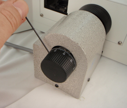
Remove the left fine focus knob from the microscope as follows:
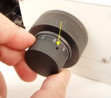
a) Locate small hole on knob.
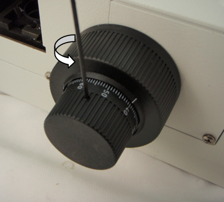
b) Use 1.5mm Allen Wrench to loosen the knob set screw.
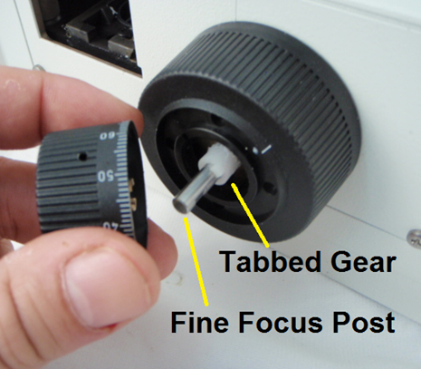
c) Carefully remove fine focus knob. This will expose the fine focus post and the tabbed gear.
Part 2 - Installing the Baseplate
[ ]
]
a) Locate the two parts baseplate and adjustment bar and assemble if as shown in figure 2a (may already be assembled).
b) Place the Baseplate/Adjustment Bar assembly so that the Adjustment bar is under the microscope and the Baseplate is lined up under the Knob on the left side of the microscope as shown in 2b.
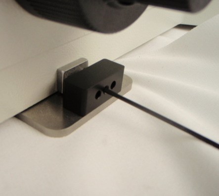
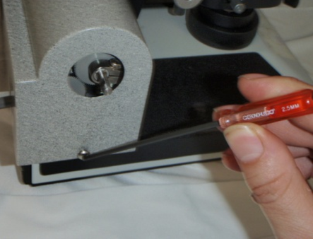
c) Using a 1.5mm Allen wrench lightly tighten the adjustment bar set screw (figure 2c), on the right side of the microscope, so that it holds onto the microscope - but can still be moved around to adjust position for proper alignment.
d) Use a 3mm allen wrench to slightly loosen two baseplate vertical adjust screws to allow for aligning Z-Drive unit. Loosen the screw just enough so that the adjustment bar can slide easily.
Part-3 Installing the Motor Drive


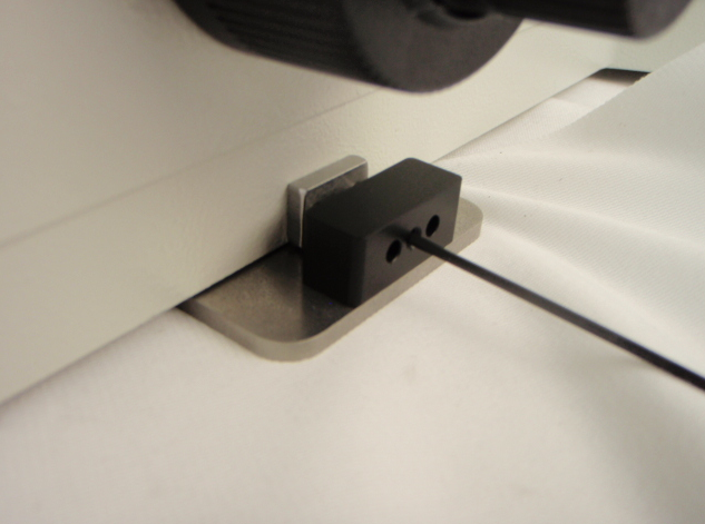
a) Locate the Tab on the bottom of the Z-Drive Alignment Arm, this will eventually go into the slot on the Baseplate (Figures 3a & 3b).
b) Note that eventually the adjustment arm will secure to the baseplate so that the tab goes into the slot.
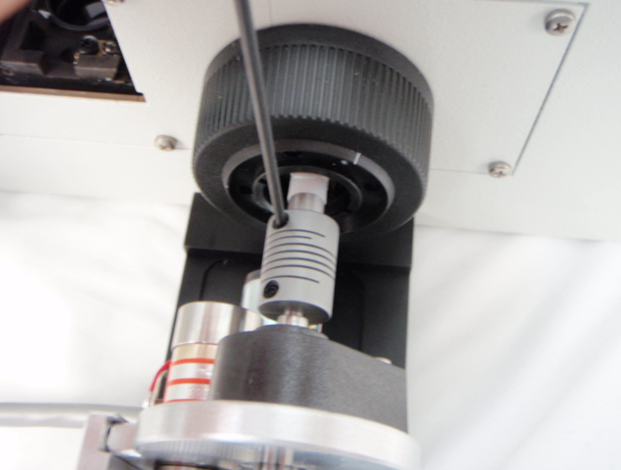
c) Holding the fine knob on the left side of the microscope, carefully slide the flex shaft coupler over the fine focus post.
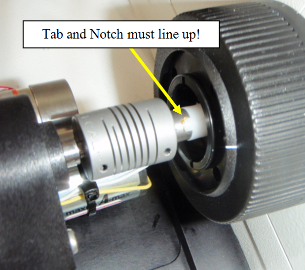
d) Aligning the notch and tab, push the shaft coupler till the unit is snug up against the tab as shown in figure 3d.
e) Attach the Z-Drive adjustment bar to the baseplate using the 4mm socket head horizontal adjustment screw with the 3mm hex wrench. The horizontal screw should be tightened till the adjustment bar tab will easily slide in the slot in the baseplate.
Part-4 Aligning the Motor Drive
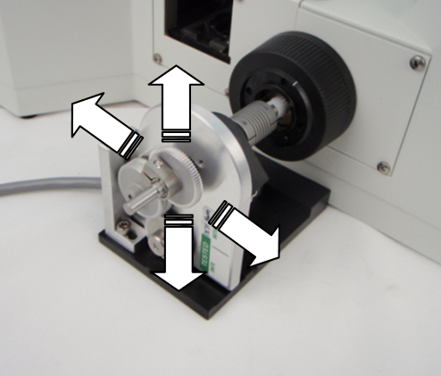
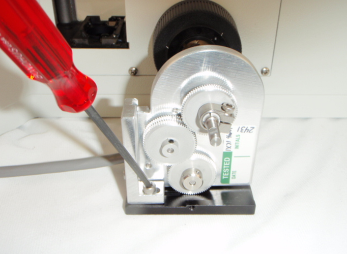
a) Slide the motor drive up and down, forward and backward slightly while turning the right fine focus knob until it is in the position where minimum drag is felt on the right focus knob (figure 4a).
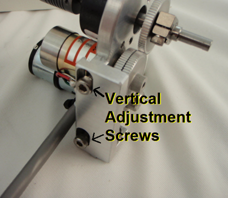
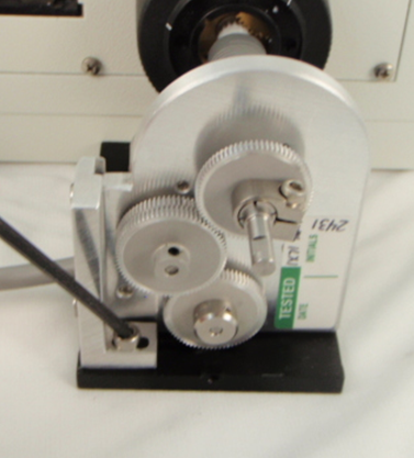
b) Once aligned, secure the motor drive into position by tightening the horizontal and vertical adjustment screws(figures 4b & 4c).
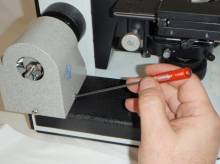
c) Once aligned, lock the baseplate into position by tightening the set screw on the right hand side of the scope with a 1.5mm screw.
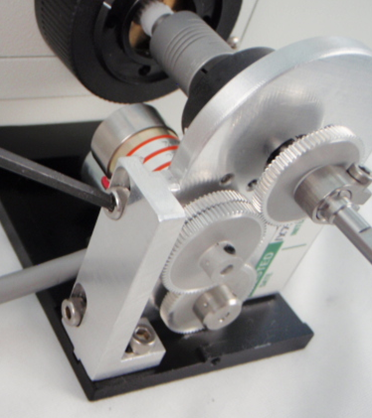
d) Once the drive unit is aligned, and alignment screws tightened, ensure the flex shaft notch is still up against the tab (figure 3d) and tighten the drive shaft clamp, as shown in figure 4d below using a 2mm hex wrench. Repeat Steps a-d till minimum drag is felt on right fine focus knob.
e) Tighten the set screws on the flex couplers using a 2mm hex driver as shown in figure 4e. Double check and ensure that the vertical / horizontal alignment screws, and baseplate set screw are tight.
Part 5-Installing the motor drive cover plate & fine focus knob.
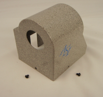
a) Locate the motor drive cover and the 2 3mm button head screws shown in figure 5a. You might have to remove the 2 screws from the baseplate holes. Place the cover over the motor drive.
b) Using one of the 3mm button head screws, secure the cover to the baseplate on the side as shown in figure 5b with a 2mm screwdriver.
c) Use the other 3mm button head screw, secure the cover to the baseplate on the front as shown in figure 5c.
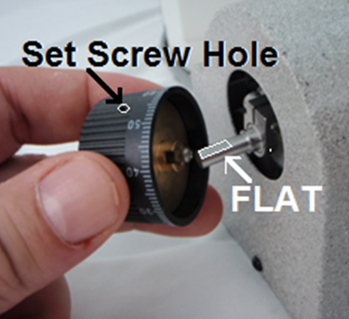
d) Lining up the set screw hole with the flat spot on the fine focus extension shaft, slide the microscope fine focus knob over the Z-Drive shaft extension and press it on all the way (figure 5d). Note: You may have to loosen the set screw to get the knob to slide on all the way.
e) Use the 1.5mm screwdriver to tighten the knob set screw as shown on figure 5e.
This completes the procedure for installing the ASI motor drive on to the Leica DMIL Microscope.