Table of Contents
Leica Aristoplan Microscope Motor Drive Installation
Motor Drive Installation
This procedure steps you through the installation and alignment of the ASI motor drive onto the Leica Aristoplan microscope. The following tools are required for this procedure:
- 1.5 mm Allen wrench ( Provided )
- 3.0 mm Allen wrench ( Provided )
- 5/64 mm Allen wrench ( Provided )
- 7/64 mm Allen wrench ( Provided )
- 1/16 mm Allen wrench ( Provided )
Preparing The Microscope
In this part of the procedure the left fine focus knob will be removed from the microscope.
Prior to removing left fine focus knob, the microscope stage should be fully lowered. To do this, rotate the coarse knob to lower the stage all the way down.
Note: the terms left and right refer to the sides of the microscope as viewed from the front.
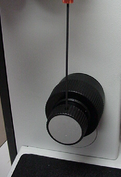
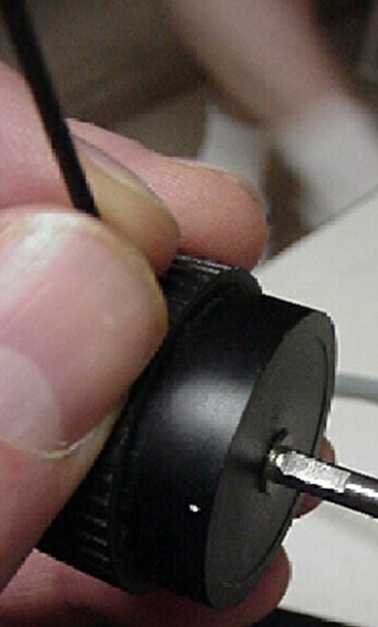
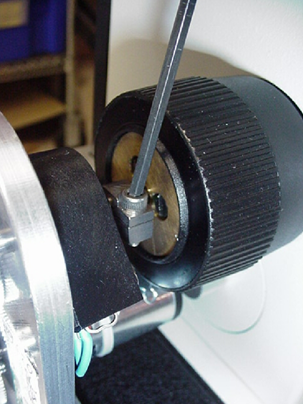
1) Remove the left fine focus knob by using the 1.5mm hex wrench to loosen the set screw as shown above in figure 1. Then pull the knob off of the fine focus shaft as shown in figure 2.
Installing the Drive and Back Plate Assembly
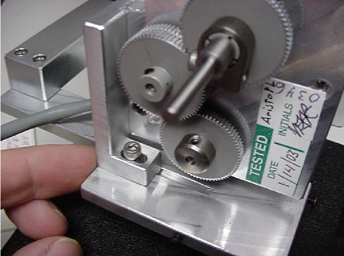
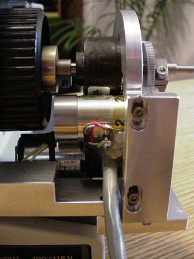
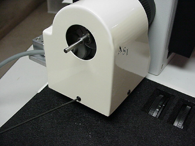
Locate the motor drive and the back plate. If the drive is not installed onto the back plate, install it as shown in figure 3. Do not completely tighten the horizontal adjustment screw shown in figure 3. Leave it loose enough so that the drive can easily slide within the grove. Also loosen the vertical adjustment screws shown in figure 4 so that the drive can easily slide within the grove. At this time, also loosen the screw on the fine focus shaft clamp that is located near the black encoder. This clamp is showed installed in figure 5.
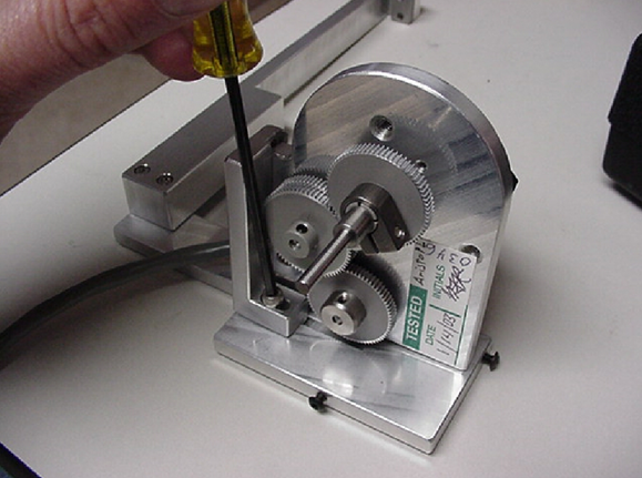
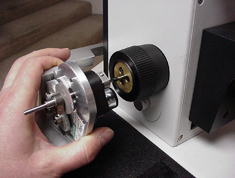
In this step we will install the ASI backplate and motor drive assembly as a unit as shown in figure 6. The ASI back plate will be installed and clamped to the back of the microscope as shown in figures 7 & 8 only after the motor drive is clamped onto the fine focus shaft of the microscope as shown in figure 5.
- Install the ASI backplate and motor drive assembly as a unit as shown in figure 6.
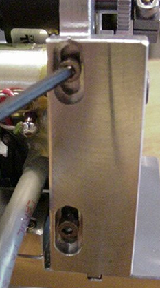
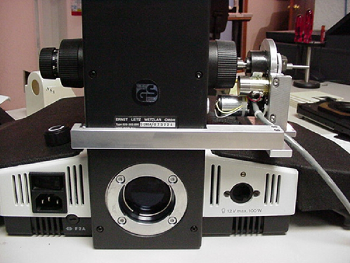
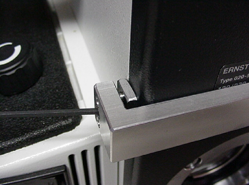
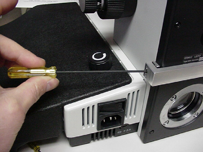
- Slide the back plate up against the rear of the scope as shown in figure 7 and lightly tighten the clamp as shown in figure 8.
- Securely tighten the fine focus shaft clamp as shown in figure 5. Please note that this clamp must be securely tightened or the drive may slip.
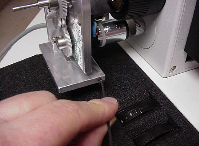
- After securely tightening the fine focus shaft clamp as shown in figure 5. Loosen the back plate clamp shown in figure 8 and adjust it so that the drive is aligned as shown in figure 9 and the vertical adjustment screws are also centered as shown in figure 10. When in position, tighten the back plate clamp as shown in figure 8 & 11 to hold the back plate in the correct position.
- Tighten the vertical and horizontal adjustment screws in their mid positions as shown in figures 9 & 10.
Aligning the drive
After securing the back plate, and the vertical and horizontal adjustment screws, check for proper drive alignment by rotating the right fine focus knob. The drive is usually self-aligning and when properly aligned no drag is felt, other than that caused by the gears, while rotating the fine focus knob. If there is any drag felt at any particular point while rotating the right fine focus knob repeat the alignment procedure by loosening the horizontal and vertical adjustment screws and repositioning the drive. After re-alignment, recheck for minimum drag on the fine focus shaft by again turning the right fine focus knob.
Step 6 - Installing the cover & left fine focus knob
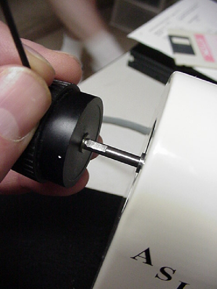
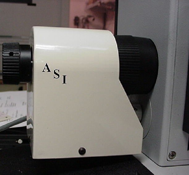
Remove the two screws from the edges of the drive assembly as shown in figure 12. Locate the ASI cover plate. Place it in position over the motor drive assembly, as shown in figure 13, and secure it with the screws just removed. Place the left fine focus knob over the protruding end of the drive shaft, as shown in figure 14, and secure it in place with the 1.5 mm Allen wrench. Please note that the set screw needs to mate with the flat part of the shaft as shown in figure 14 to prevent the fine focus knob from slipping.
Connecting the Motor Drive to the Controller and Computer
Please refer to the wiring drawings and diagrams given in the manual
Tools Needed:
- Small slotted screw driver
- Locate the drive cable. Connect one end of the drive cable to the pigtail extending from the motor drive near the microscope and the other end to mating connector on the back of the Microscope Focus Controller, or MS-2000 unit labeled “Drive”. Secure the cable to the drive by tightening the screws at each end of the connector.
- Locate the computer interconnect cable. Connect one end to the mating connector on the back of the controller labeled “Serial In”. Connect the other end to the appropriate serial output connector on your computer.
- Plug in the power cord / power supply
This completes the steps necessary to interconnect the ASI motor drive, focus controller and computer. Please refer to the operation section of this manual before using the unit