FW-1000 Optical Encoder Adjustment
(Be sure to have a copy or the FW-1000 Manual for the final software alignment of the Filter Wheel)
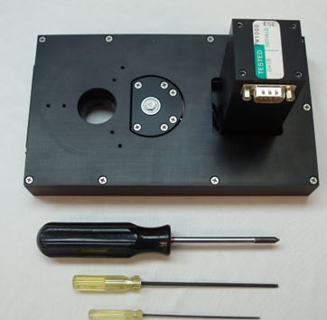
Step 1: You will need the following tools to adjust the encoder: a Phillips screwdriver, a 3/32” Allen wrench and a.050” Allen wrench.
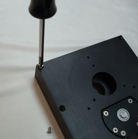
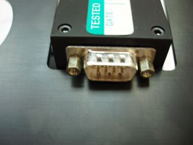
Step 2: Remove the nine 4-40 flat head Phillips screws from the case and remove the top cover. The cover should just clear the motor housing. On some older models, the cover will not clear the housing and the DB-9 connector may have to be removed with a 3/16” wrench first.
Step 3: Remove the filter wheel body from the housing with a 3/32” Allen wrench. Don’t remove the button head screws entirely as they will hold the lower felt washers in place when the unit is removed.
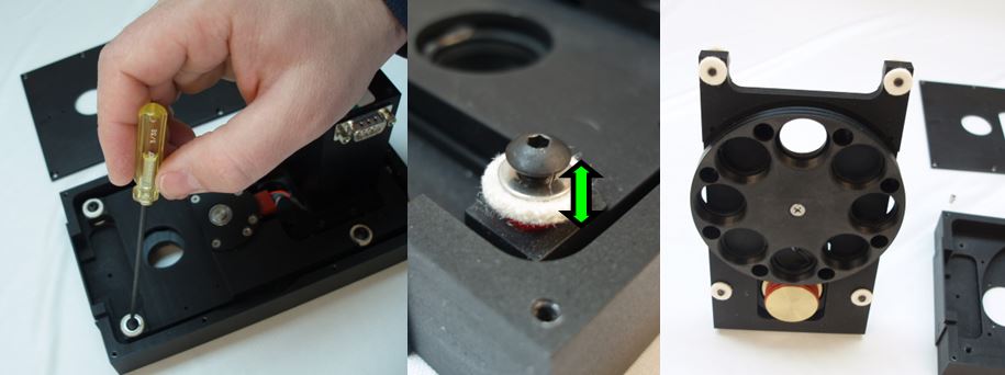
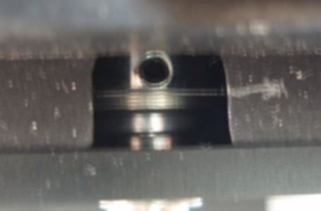
Step 4: Locate and mark the position of the filter wheel Optical encoder disk with a pencil next to its opening. Next, rotate the wheel manually until the .050” set screw is visible from the opening.
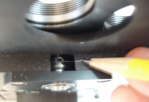
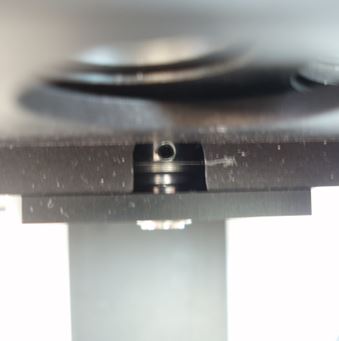
Step 5: Insert a .050” Allen wrench into the encoder disk set screw and loosen the screw. Rotate the filter wheel for ½ of the opening distance, (approximately 1”), while holding the Allen wrench and encoder wheel in place. Check that the encoder wheel is still at the axial distance marked by the pencil line and reset the setscrew.
Step 6: Finally adjust the software offset to center the wheel with the opening in the body. The instructions are in the filter wheel manual and reprinted here.
- Set up the wheel so that the filters can be observed in the aperture in the housing. (The body should still be out of the case at this point).
- Set up serial communications to the controller and verify operation. (Both the serial and control cables should be plugged in).
- Issue the “OF” command (without a number) to see the present setting of offset.
- Issue the “HO” command to Home the wheel.
- Note whether the filter at position zero is centered in the housing aperture. If so, you are done. Save the setting if you have changed the setting, (Step 8).
- Otherwise, make a guess at the correct value for the offset between 1 and 128 for 8 position wheel and 1-170 for 6 position wheel. Adjust your guess based upon your last try. Issue the offset command with your guess; e.g., “OF 65”.
- Issue the “HO” command to Home the wheel and go to Step 5.
- Issue the ‘RS” (Ram Save) command to save your setting to flash memory.
- Turn the controller off – Wait a few seconds and turn the controller back on. The wheel should “Home” upon power–up and filter “0” should be centered in the housing aperture.
Now that the wheel is centered, replace the wheel body into the case in reverse order. The button head screws that hold the four corners of the body must be completely hand tightened and then turned back ½ turn to allow the felt to absorb vibrations. Finally, repeat part 9 above and check that the wheel is still centered upon power up.