Table of Contents
Basic CRISP alignment for OEM systems
Setup as follows:
- Representative test sample in place
- Recording camera present with no filters between CRISP dichroic and camera
- CRISP cover and light shield removed for access to the LED fastener
- ASI-Console (software)
Basic alignment steps are:
- Align the CRISP LED source to the camera/ microscope
- Align the CRISP splitting mirror to the center of the aperture
- Adjust the detector position for optimum performance.
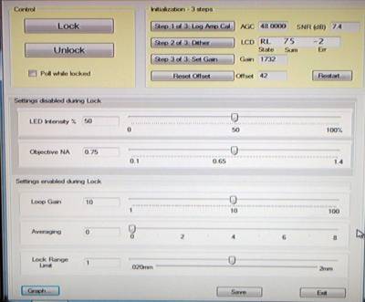
Use ASI-Console CRISP control “Step 1” to turn on the LED with sufficient brightness that it is easily observable with the camera.
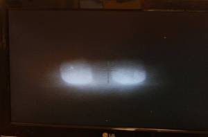
Photo shows LED mask focused in center of Camera – also the substrate is in focus. This shows the nominal correct placement and tilt of the LED.
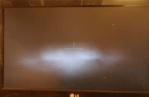
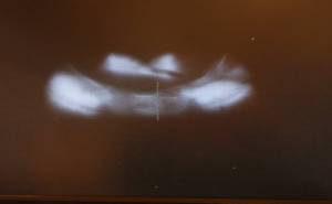
If you focus the microscope higher or lower, Figure 2 & 3, the mask image morphs into a blur. In one direction, the LED die comes into focus. When the splitting mirror is correctly adjusted, the bulk of the light will translate laterally (vertically in the photos).
Align the CRISP LED source to the camera/ microscope
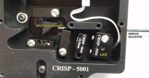
- Turn MIRROR ADJUSTER counter clockwise a few turns to move mirror fully in front of iris aperture.
- Focus the microscope on the sample surface and verify that the LED mask image is also in focus.
- Loosen the single Allen pan-head screw holding the LED in place. Tilt and slide the LED holder so that you meet the following conditions:
- LED image is centered in camera frame.
- Tilt LED so maximum brightness is seen through the LED mask.
- Tilt / position LED image so that any reflected glare from other optics is well separated from the LED mask image. This last step may require a compromise for a) and b) above and will depend on the sensitivity of the application to any stray reflected glare.
- Tighten the Allen head screw to lock the LED in place.
Align the CRISP splitting mirror to the center of the aperture
- Adjust camera exposure so that LED mask image is not saturated – linear camera response.
- Turn MIRROR ADJUSTER clockwise until the image intensity of the LED mask drops about in half.
- The Tip of the mirror should be close to the center of the iris aperture.
- Place CRISP control in the Step 2 “Dither” state. Observe the lateral motion of the LED mask image. There should be observable lateral motion – not just symmetric focus/defocus.
- Adjust main thumb screw for maximum ERR number.
- Click Step 3 “Set Gain” and wait a few seconds for it to finish.
- Click Step 1 “Log Amp Cal” to re-calibrate the light intensity. Verify that the SUM is about 75 (+/- 15)
- Turn MIRROR ADJUSTER slightly, looking for maximum SUM signal. Repeat steps 6) and 7).
Adjust the detector position for optimum performance
1)Click Step 2 “Dither” state. Adjust the main CRISP adjusting Thumb Screw for maximum ERR number. 2)Click Step 3 “Set Gain” and wait a few seconds for it to finish. 3)Re-focus microscope on sample and set the Z-axis controller position to Zero. (HERE Z=0) 4)Be sure NA setting is correct for the objective and click “GRAPH” button.
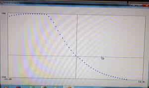
CRISP graph of the focus function for a “deep” scan +/- 60um. Operating position is where the curve crosses the vertical line at Z=0. The horizontal line shows the position where the two detectors have the same signal level (zero for the vertical axis).
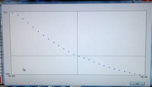
CRISP graph for normal-depth scan. 20X NA 0.75 objective on silicon Good operation point with +/-27um operating range and near zero offset.
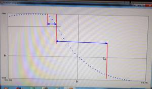
5)Choose and operating point and adjust the main CRISP adjusting Thumbscrew to get there. If you only adjust for maximum ERR number, then the point you choose will be at the steepest part of the focus curve. Sometimes this can be very close to where the curve makes a sudden change in slope.
This figure shows the problem of choosing just maximum ERR to determine the operating point. The center vertical red line is at roughly the maximum value of the focus curve slope. If the operating point was at the center red line, then the system could correct for errors over a range of errors of about 7um in one direction and about 45um in the other direction. This is not robust. To operate at the center red line, the system would need to include a significant OFFSET because one detector will have much more light on it than the other.
Better is to move the operating point to where there is approximately zero offset but on a portion of the curve with a lower slope. Lower slope means that the ERR number in the STEP 2 “Dither” operation will be smaller than the peak value. You should be able to “move down the curve” by adjusting the Thumbscrew for slightly lower ERR number and then repeating the STEP 3 “Set Gain” operation. You should observe after the “Set Gain” that the calculate OFFSET reduces as well.
6)Repeat adjusting the Thumbscrew to lower slightly the ERR number and also gradually bring the OFFSET number close to zero. Repeat the GRAPH function and look for something like Figure 6.

