Assembly Instructions for the RAMM
Notice: RAMM systems are usually shipped intact since at least 2015 so these instructions are obsolete and rarely needed.
Be sure to locate and remove all parts and tools from the packaging.
Part 1: Parts list
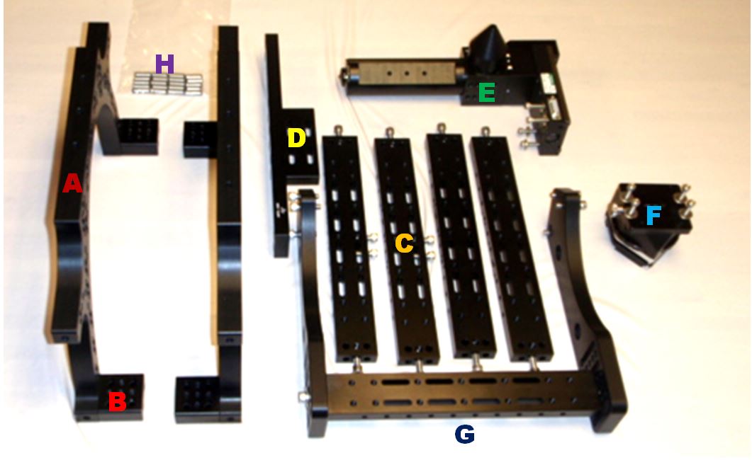
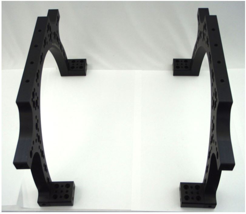
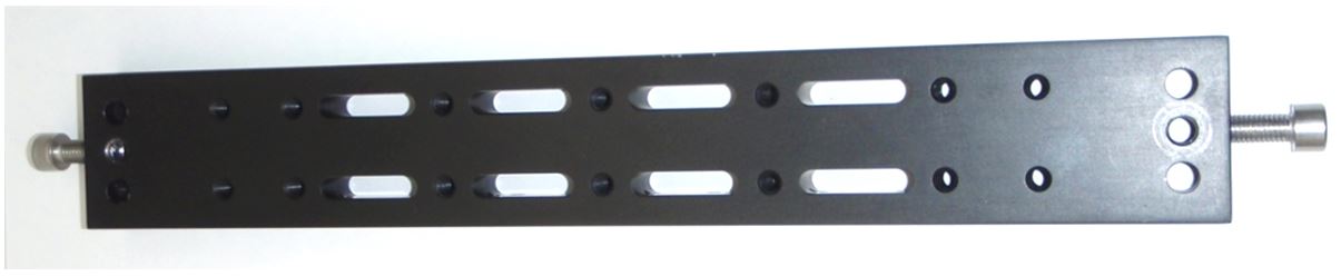
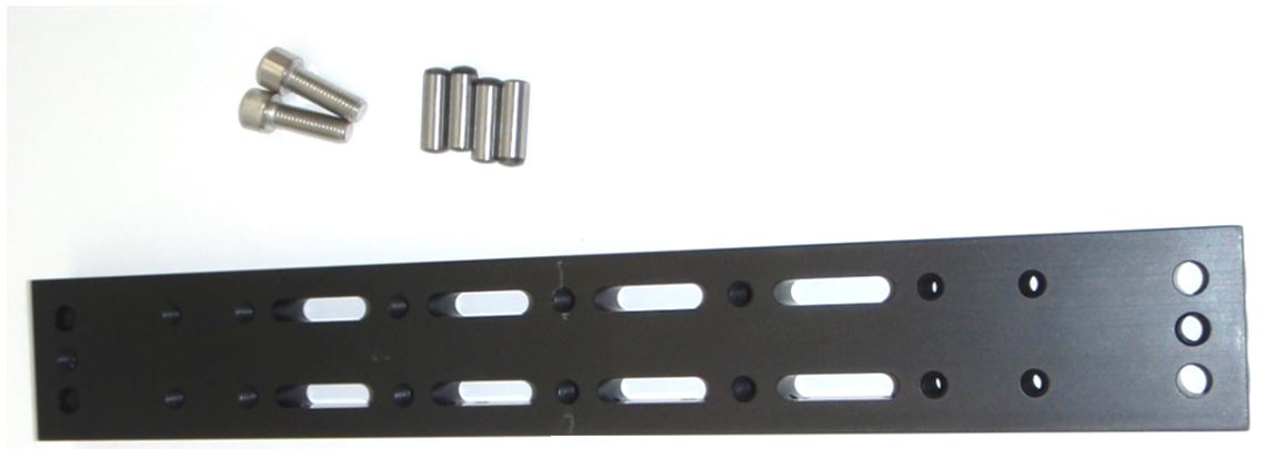
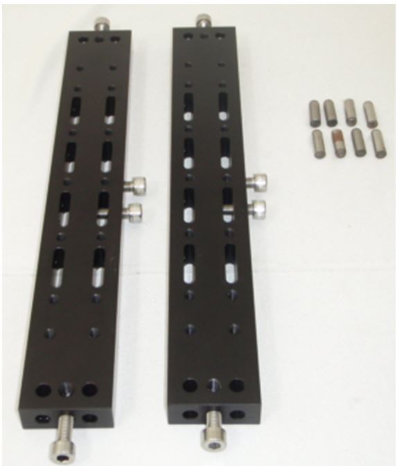
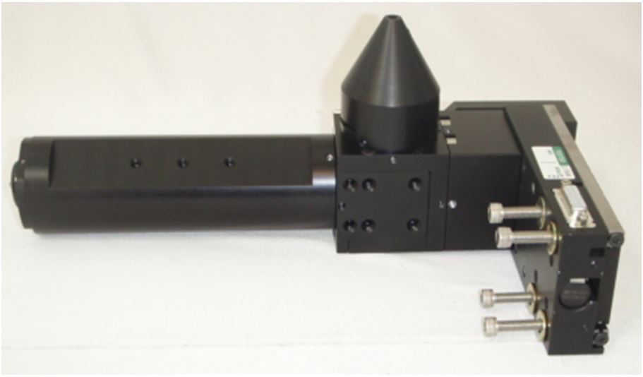
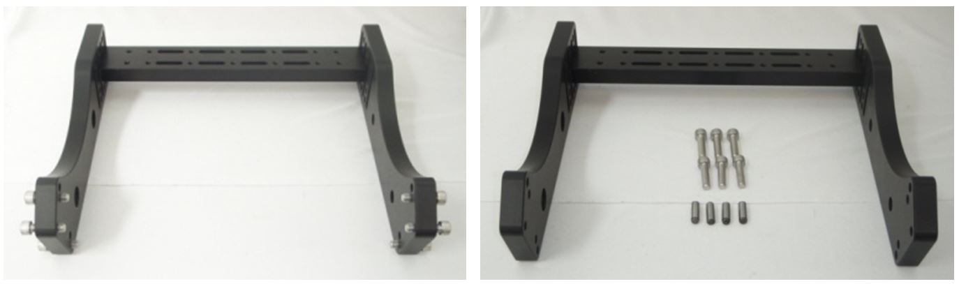
Step 1: Remove all the parts from the packaging. They should include: two Upright Arches, (A), with four Foot Clamps, (B), attached by 8 cap screws, four Cross Bars, (C), with 12 cap screws attached, one Alt Cross Bar with Cross Bar Mount attached, (D), with 3 cap screws, one M.I. Microscope and LS-50 assembly, (E), with 4 cap screws and 4 washers, one C.D.Z., (F) with 4 cap screws and 4 washers, one Riser assembly, (G), (2-Risers and one Riser Cross Bar), with 8 cap screws and 2 washers, 20 Alignment Pins, (H), and two hex wrenches 5mm and 6mm.
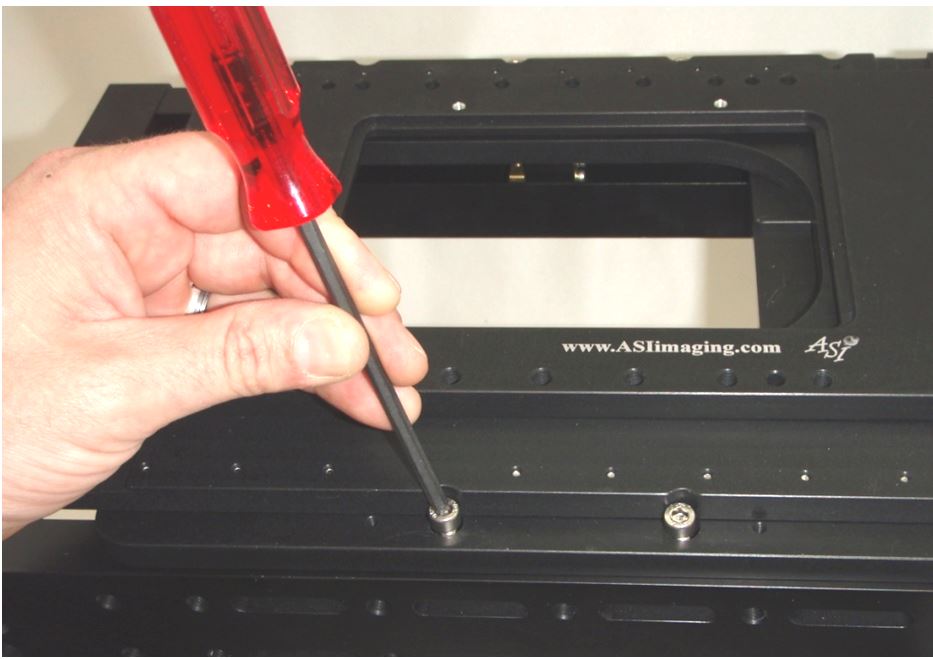
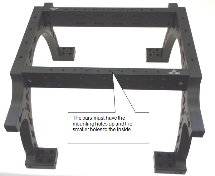
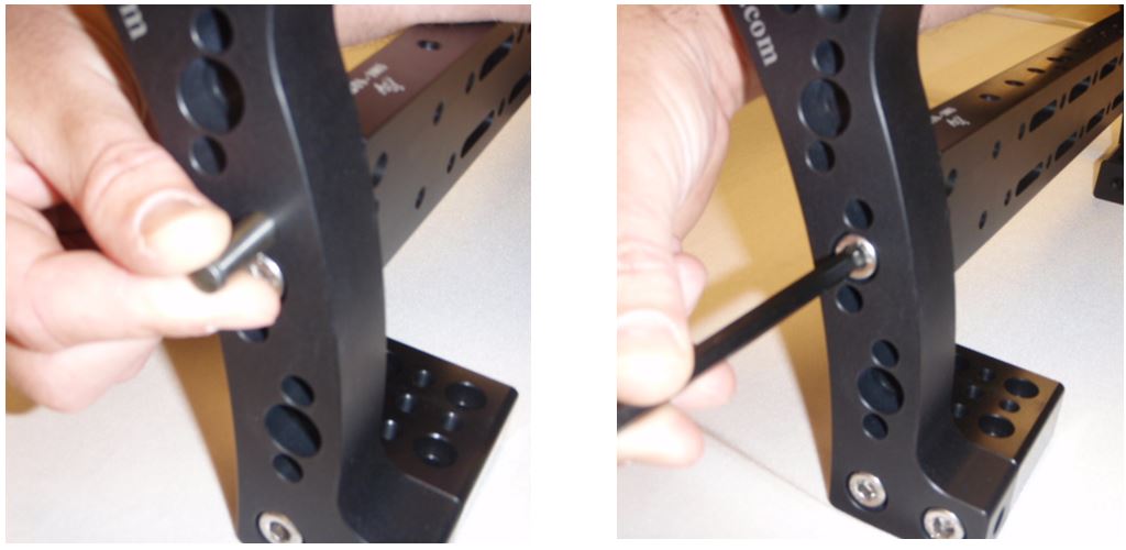
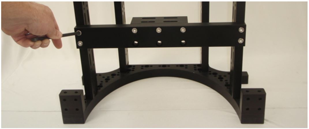
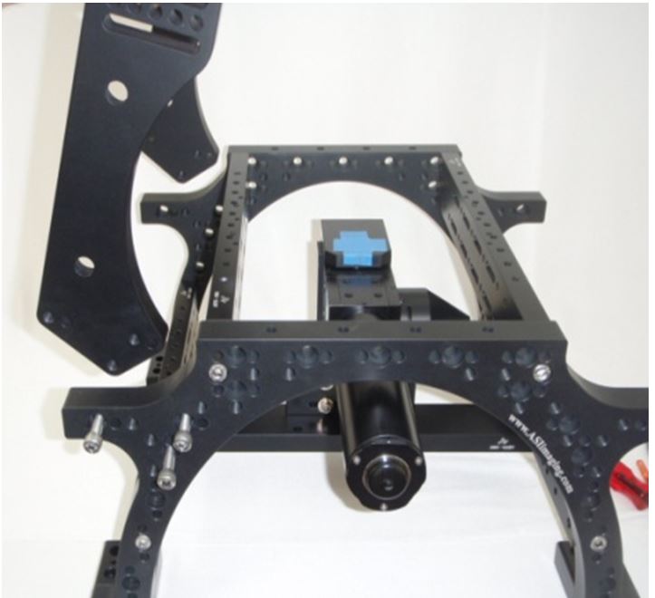
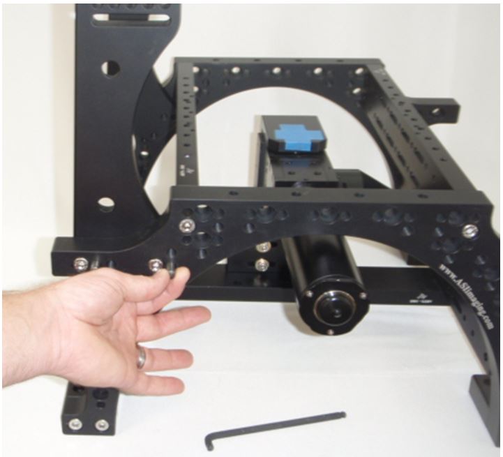
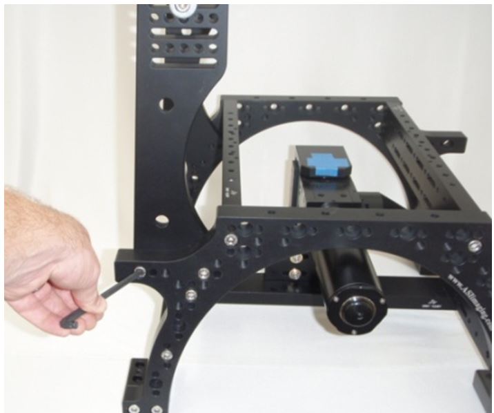
Step 2: Start with the two arches as shown in figure 2 placed the distance of a cross bar apart, (see figure 2). Add the two cross bars, (see figure 3a), that have cap screws only in their ends to the uppermost corner holes in the arches, (see figure 4a, b and c). The bars must have the mounting holes up and the smaller stage mounting holes to the inside, (see figure 5). Each bar needs four alignment pins and two cap screws, (as in figure 3b and 4a).
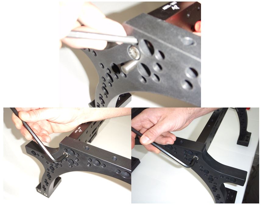
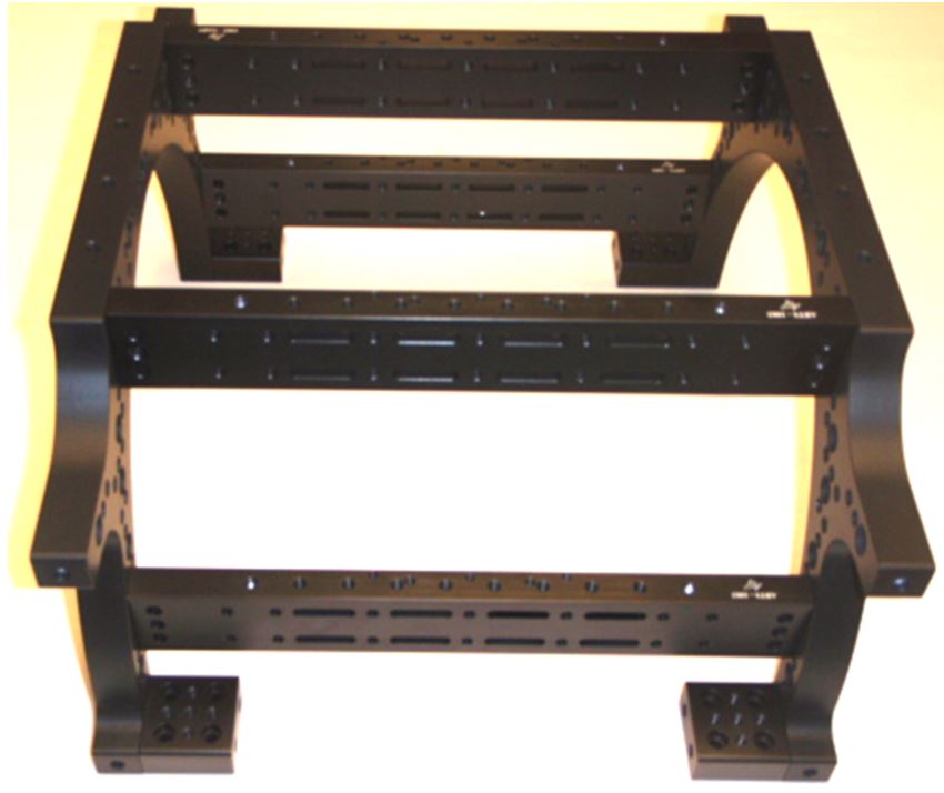
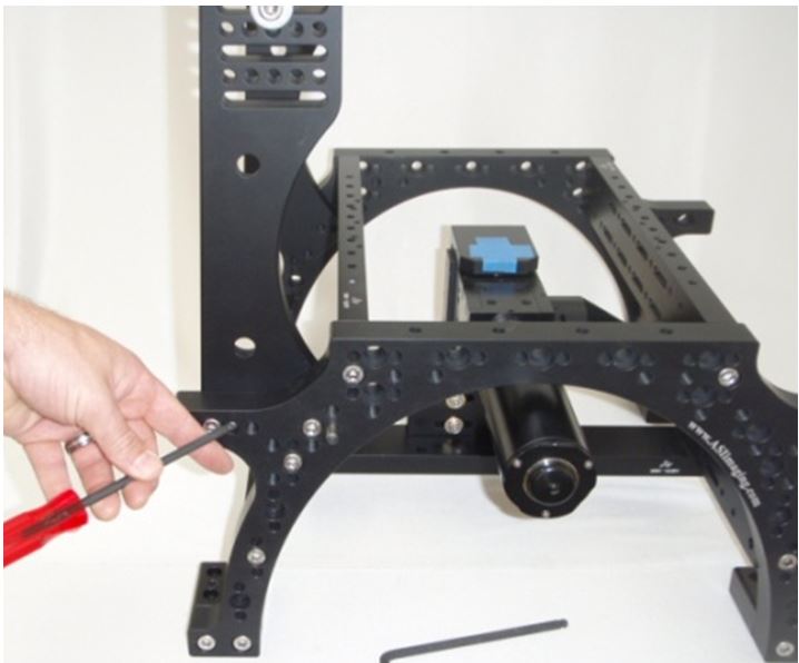
Step 3: Add the next two cross bars with 2 extra cap screws to the upright arches at the second hole from the bottom. Use the same alignment pins on these bars and have the cap screws point down, (see figure 6 and 7a, b, and c).
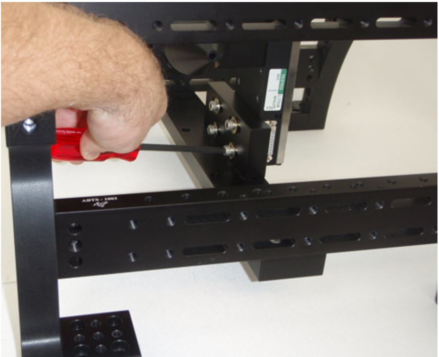
Step 4: Add the alt cross bar and mount to the cap screws on the bottom of the lower bars.
Step 5: Add the Modular Infinity Microscope to the alt cross bar and secure using the attached 4 cap screws and washers.
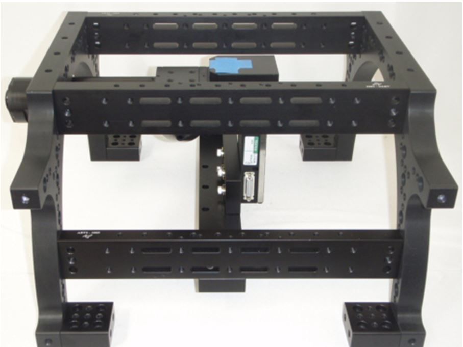
Step 6: Add the Riser assembly to the top of the RAMM with the four alignment pins and the provided 6 cap screws, (as seen in figures 9 and 10).
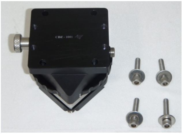
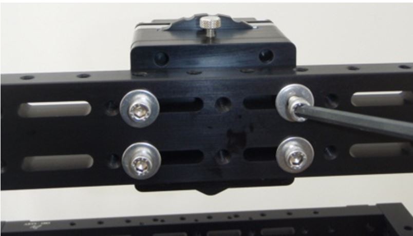
Step 7: Add the CDZ to the Riser assembly and center with the four cap screws, (as seen in figure 11 and 12).
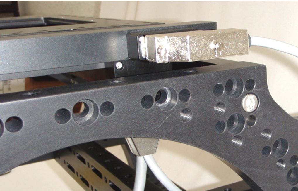
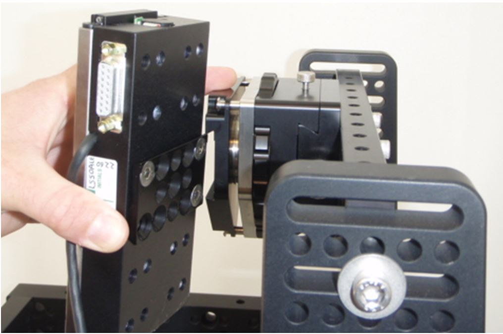
Step 8: Add the Ls-50 with dove tail to the CDZ and lock in place.
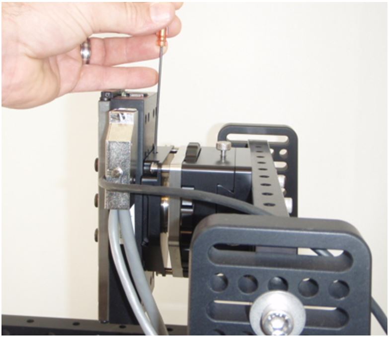
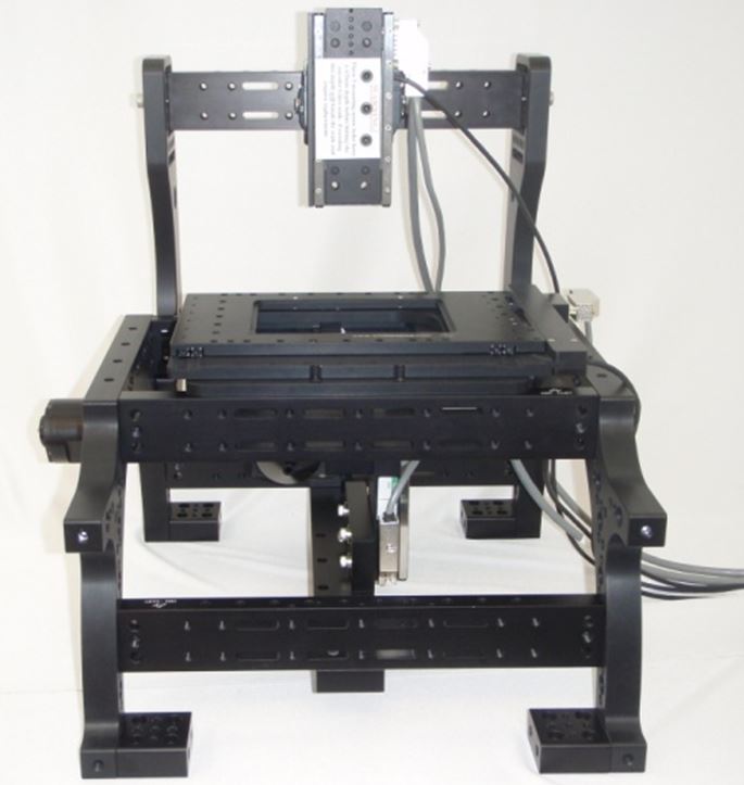
Step 9: Mount the stage to the RAMM system with the supplied cap screws and connect the cables to the stage and both of the LS-50s.