Table of Contents
Setting Limit Switches on Various XY Stages
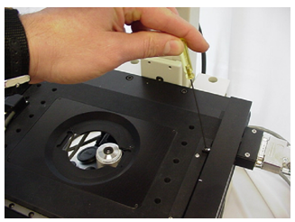
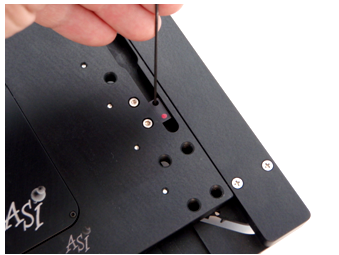
There are two sets of limit switches on nearly all XY stages. The two on the top of the stage as shown figures 1a & 1b below are used to limit the range of motion in the Y-axis. The two shown figure 2 a & 2b below are used to limit the range of motion in the X-axis, and these are located on the bottom of the stage. The X-axis limit adjustment setscrews can be accessed by moving the Y-axis towards the front of the microscope. You will need an Allen wrench that was supplied with the stage to make these adjustments.
Do not over-tighten the limit switch’s setscrews. Tighten only until the limit assembly does not move. Over-tightening the upper assemblies causes them to bend outward and even break. Also, ensure that the upper limit assemblies are held firmly against their rail to prevent them from touching or scratching the leadscrew cartridge.
- Inverted MS2000 stages with embedded limits(for Axiovert, Axiovert35 and AxioObserver etc)
-
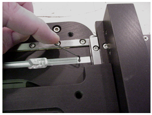
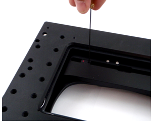
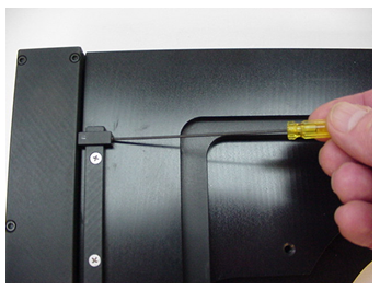
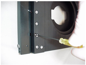
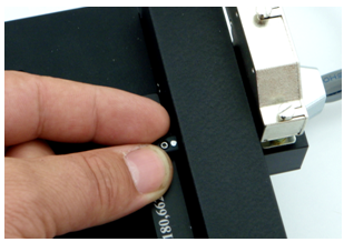
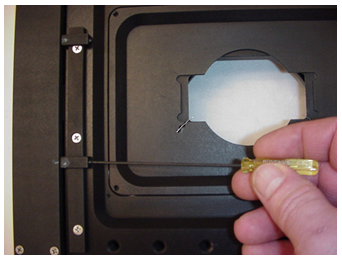
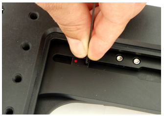
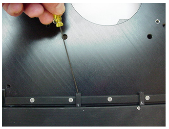
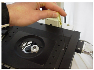 Figure 1a. Loosening setscrew so that you can move the Y-axis lower limit switch sensor. Do not Over-tighten
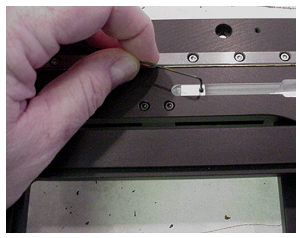
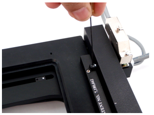
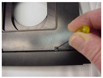
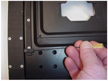
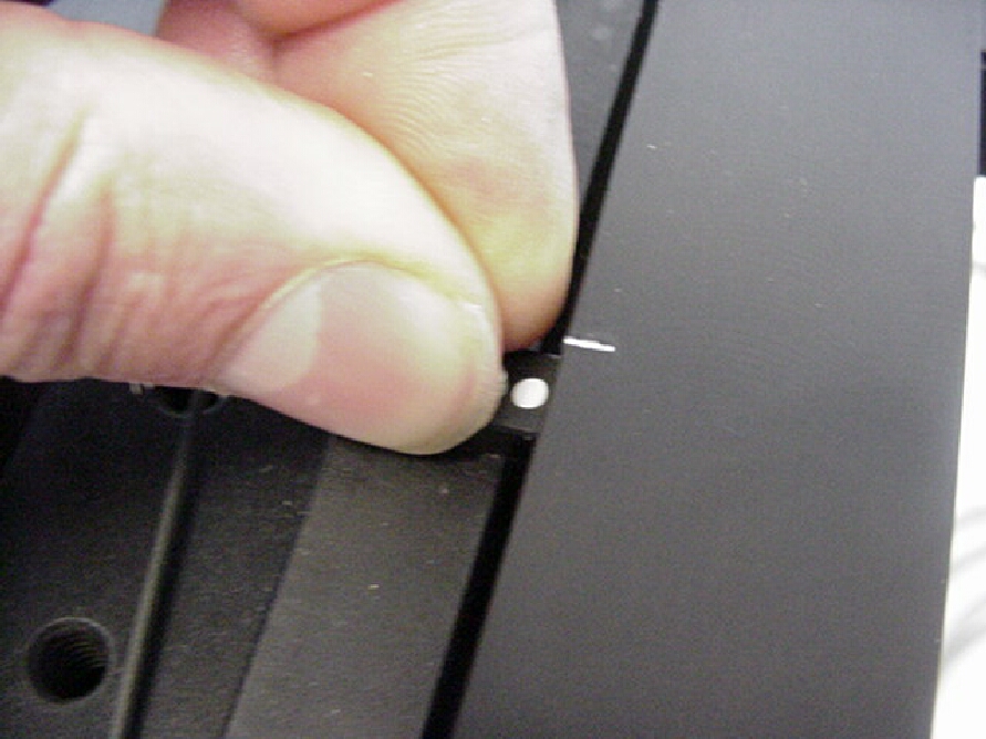
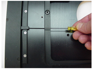
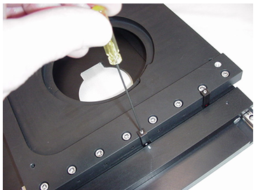
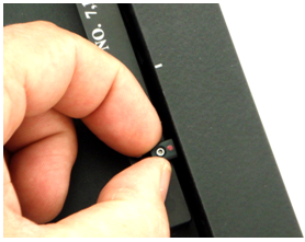
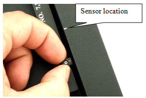
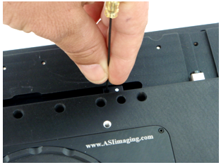
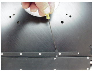
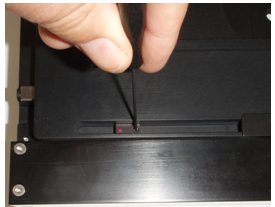
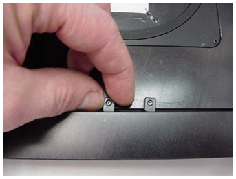
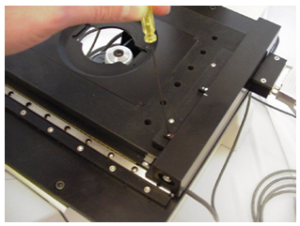 Figure 1b. Loosening setscrew so that you can move the Y-axis upper limit switch. sensor. Do not Over-tighten
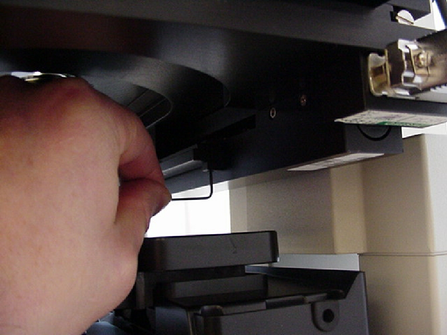
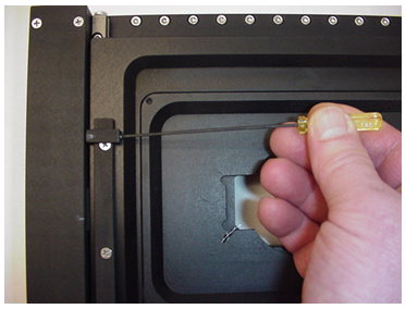
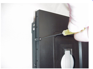
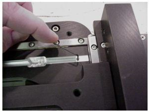 Figure 2a. Loosening setscrew so that you can move the X-axis lower limit switch sensor. Do not Over-tighten
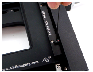
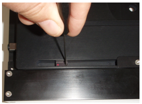
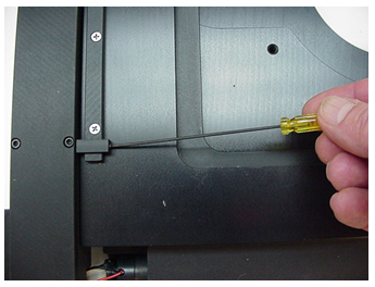
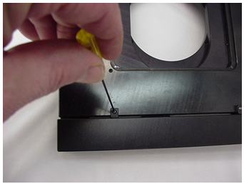
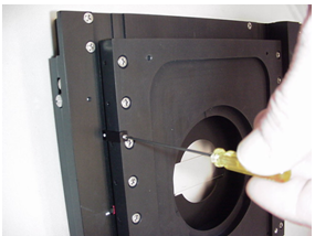
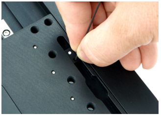
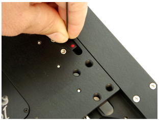
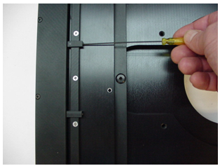
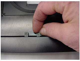
 Figure 2b. Loosening setscrew so that you can move the X-axis upper limit switch sensor. Do not Over-tighten
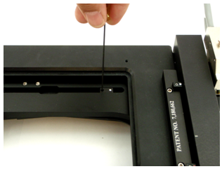

- Inverted MS2000 stages ( for Axiovert 200 HEMQ )
-
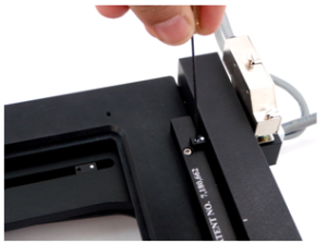 Figure 1a: Loosen the setscrew so that you can move the Y-axis lower limit located at the rear right of stage. Do not over-tighten.
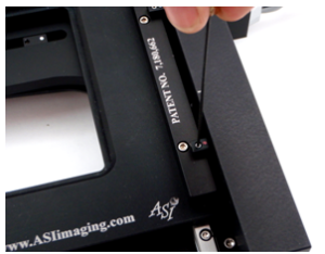 Figure 1b: Loosen the setscrew so that you can move the Y-axis upper limit located at the front right of stage. Do not over-tighten.
 Figure 2a:. Loosen the setscrew so that you can move the X-axis lower limit located at the right rear of the middle plate of stage. Do not over-tighten.
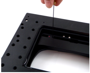 Figure 2b: Loosen the setscrew so that you can move the X-axis upper limit located at the left rear of the middle plate of stage. Do not over-tighten.
- MS2500 or FlatTop Inverted Stage
-
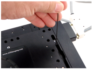 Figure 1a: Loosen the setscrew so that you can move the Y-axis lower limit located at the rear right of stage. Do not over-tighten.
 Figure 1b: Loosen the setscrew so that you can move the Y-axis upper limit located at the front right of stage. Do not over-tighten.
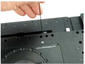 Figure 2a. Loosen the setscrew so that you can move the X-axis lower limit located at the right rear of the middle plate of stage. Do not over-tighten
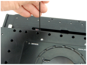 Figure 2b: Loosen the setscrew so that you can move the X-axis upper limit located at the left rear of the middle plate of stage. Do not over-tighten.


- Inverted MS2000 stages (for TE-2000 )
-
Figure 1a: Loosen the setscrew so that you can move the Y-axis lower limit located at the rear right of stage. Do not over-tighten.Figure 1b: Loosen the setscrew so that you can move the Y-axis upper limit located at the front right of stage. Do not over-tighten.
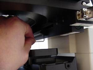 Figure 2a: Loosen the setscrew so that you can move the X-axis lower limit located at the right rear of the middle plate of stage. Do not over-tighten.
 Figure 2b: Loosen the setscrew so that you can move the X-axis upper limit located at the left rear of the middle plate of stage. Do not over-tighten.
- MS-8000 stage
-
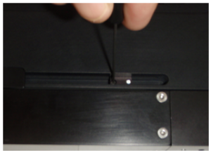 Figure 1a. Loosen the setscrew so that you can move the X-axis lower limit located at the bottom right of the stage. Do not over-tighten.
 Figure 1b. Loosen the setscrew so that you can move the X-axis upper limit located at the bottom left of the stage. Do not over-tighten.
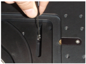 Figure 2a. Loosen the setscrew so that you can move the Y-axis lower limit located at the top right of the stage. Do not over-tighten.
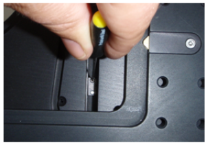 Figure 2b. Loosen the setscrew so that you can move the Y-axis upper limit located at the bottom right of the stage. Do not over-tighten.


- MS-8000 stage (obsolete old version)
-
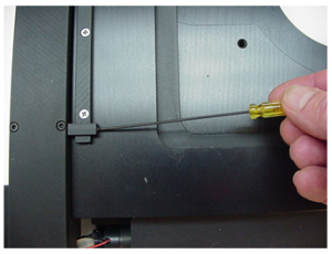 Figure 1a. Loosen the setscrew so that you can move the Y-axis lower limit located at the front left of stage. Do not over-tighten.
 Figure 1b. Loosen the setscrew so that you can move the Y-axis upper limit located at the rear left of stage. Do not over-tighten.
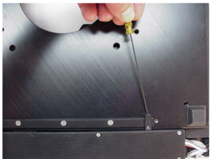 Figure 2a. Loosen the setscrew so that you can move the X-axis lower limit located at the bottom left front of the stage. Do not over-tighten.
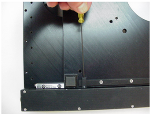 Figure 2b. Loosen the setscrew so that you can move the X-axis upper limit located at the bottom right front of the stage. Do not over-tighten.


- Upright MS2000 stage
-
 Figure 1a. Loosen the setscrew so that you can move the X-axis lower limit located at the front right of stage. Do not over-tighten.
 Figure 1b. Loosen the setscrew so that you can move the X-axis upper limit located at the rear right of stage. Do not over-tighten.Figure 2a. Loosen the setscrew so that you can move the Y-axis lower limit located at the bottom right rear of the stage. Do not over-tighten.Figure 2b. Loosen the setscrew so that you can move the Y-axis upper limit located at the bottom left rear of the stage. Do not over-tighten.
- Upright MS-4000 stage
-
 Figure 1a. Loosen the setscrew so that you can move the Y-axis lower limit located at the front left of stage. Do not over-tighten.
 Figure 1b. Loosen the setscrew so that you can move the Y-axis upper limit located at the rear left of stage. Do not over-tighten.
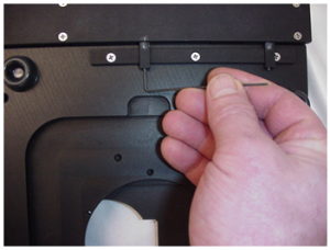 Figure 2a. Loosen the setscrew so that you can move the X-axis lower limit located at the bottom left front of the stage. Do not over-tighten.
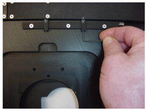 Figure 2b. Loosen the setscrew so that you can move the X-axis upper limit located at the bottom right front of the stage. Do not over-tighten.


- Upright MS-4400 Stage
-
 Figure 1a. Loosen the setscrew so that you can move the X-axis lower limit located at the front left of stage. Do not over-tighten.
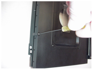 Figure 1b. Loosen the setscrew so that you can move the X-axis upper limit located at the rear left of stage. Do not over-tighten.
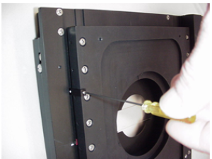 Figure 2a. Loosen the setscrew so that you can move the Y-axis lower limit located at the bottom left front of the stage. Do not over-tighten.
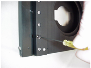 Figure 2b. Loosen the setscrew so that you can move the Y-axis upper limit located at the bottom right front of the stage. Do not over-tighten.

- MS-9500 stage
-

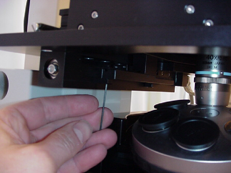
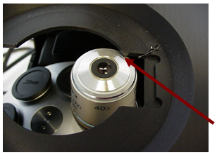
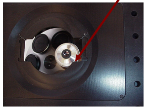
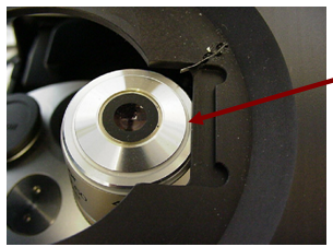
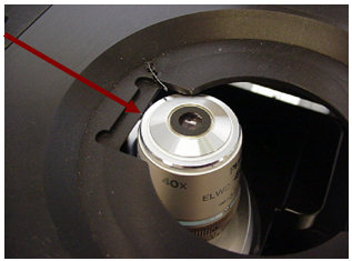
The limit switches are set at the factory to allow the longest range of travel in the X and Y axis. However, the limit switches have been designed to allow you the user to limit the range of travel of the stage. This can be done to prevent the stage from running into the microscope, or parts of the microscope such as the objective shown in the example below. Please note that if you set the limit switches as shown in the example below you will be limiting the stages travel to only scan a 25 x 75 mm slide. This is just an example and the limit switches can be set to cover any range of travel. Please also note that if the limit switches are set such that the stage encounters the mechanical limit of motion before the limit switches are reached the stage does have an over current protection. This is provided only as a safety measure, and the stage can be damaged if the limit switches are not properly set.
Please refer to the above figures 1a ~ 2b, and the figures below to set the limit switches to prevent the SI-INV-STD slide insert from hitting the objective.
Setting the Y-axis Lower Limit
Please refer to figures 1a & 1b for loosening the setscrews that secure the Y-axis limit switches.
Setting the Y-axis lower
- Inverted MS2000 stages with embedded limits(for Axiovert, Axiovert35 and AxioObserver etc)
-
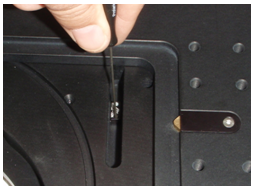
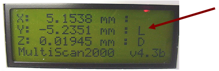
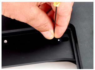
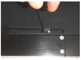
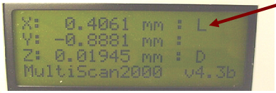
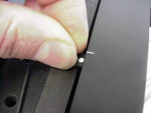 Figure 3b. After loosening setscrew as shown in figure1a. Move the sensor until the L appears in the Y-axis display as shown in figure 3c.Do not over-tighten
- Inverted MS2000 stages (for Axiovert 200 HEMQ )
-
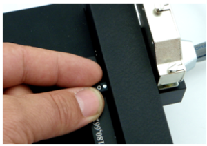 Figure 3b: After loosening the setscrew as shown in figure 1a, move the limit until the “L” appears in the Y axis display as shown in figure 3c. Do not over-tighten.
- MS2500 or FlatTop Inverted Stage
-
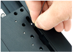 Figure 3b: After loosening the setscrew as shown in figure 1a, move the limit until the “L” appears in the Y axis display as shown in figure 3c. Do not over-tighten.
- Inverted MS2000 stages (for TE-2000 )
-
Figure 3b: After loosening the setscrew as shown in figure 1a, move the limit until the “L” appears in the Y axis display as shown in figure 3c. Do not over-tighten.
- MS-8000 stage
-
 Figure 3b. After loosening the setscrew as shown in figure 2a move the limit until the “L” appears in the Y axis display as shown in figure 3c. Tighten the set screw. Do not over-tighten.
- MS-8000 stage (obsolete old version)
-
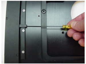 Figure 3b. After loosening the setscrew as shown in figure 1a, move the limit until the “L” appears in the Y axis display as shown in figure 3c. Do not over-tighten.
- Upright MS2000 stage
-
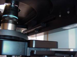 Figure 3b. After loosening the setscrew as shown in figure 1a, move the limit until the “L” appears in the Y axis display as shown in figure 3c. Do not over-tighten.

- Upright MS-4000 stage
-
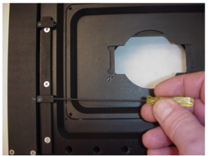 Figure 3b. After loosening the setscrew as shown in figure 1a, move the limit until the “L” appears in the Y axis display as shown in figure 3c. Do not over-tighten.
- Upright MS-4400 Stage
-
 Figure 3b. After loosening the setscrew as shown in figure 1a, move the limit until the “L” appears in the Y axis display as shown in figure 3c. Do not over-tighten.
Setting the Y-axis Upper Limit
Please refer to figures 1a & 1b for loosening the setscrews that secure the Y-axis limit switches.
Setting the Y-axis upper
- Inverted MS2000 stages with embedded limits(for Axiovert, Axiovert35 and AxioObserver etc)
-
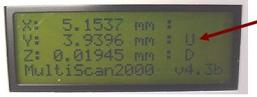
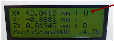
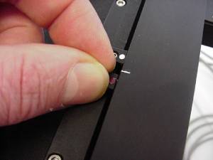 Figure 4b. After loosening setscrew as shown in figure1b. Move the sensor until the U appears in the Y-axis display as shown in figure 4c.Do not over-tighten

- Inverted MS2000 stages (for Axiovert 200 HEMQ )
-
 Figure 4b: After loosening the setscrew as shown in figure 1b, move the limit until the “U” appears in the Y axis display as shown in figure 4c. Do not over-tighten.
- MS2500 or FlatTop Inverted Stage
-
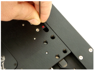 Figure 4b: After loosening the setscrew as shown in figure 1b, move the limit until the “U” appears in the Y axis display as shown in figure 4c. Do not over-tighten.
- Inverted MS2000 stages (for TE-2000 )
-
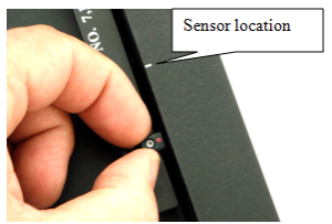 Figure 4b: After loosening the setscrew as shown in figure 1b, move the limit until the “U” appears in the Y axis display as shown in figure 4c. Do not over-tighten.
- MS-8000 stage
-
Figure 4b. After loosening the setscrew as shown in figure 2b, move the limit until the “U” appears in the Y axis display as shown in figure 4c. Tighten the set screw. Do not over-tighten.
- MS-8000 stage (obsolete old version)
-
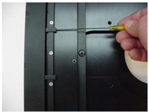 Figure 4b. After loosening the setscrew as shown in figure 1b, move the limit until the “U” appears in the Y axis display as shown in figure 4c. Do not over-tighten.
- Upright MS-4000 stage
-
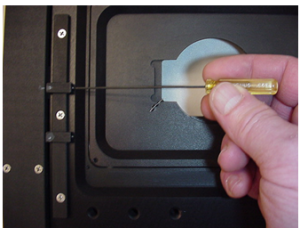 Figure 4b. After loosening the setscrew as shown in figure 1b, move the limit until the “U” appears in the Y axis display as shown in figure 4c. Do not over-tighten.

- Upright MS-4400 Stage
-
Figure 4b. After loosening the setscrew as shown in figure 1b, move the limit until the “U” appears in the Y axis display as shown in figure 4c. Do not over-tighten.
Setting the X-axis Lower Limit
Please refer to figures 2a & 2b for loosening the setscrews that secure the Y-axis limit switches.
Setting the X-axis lower
- Inverted MS2000 stages with embedded limits(for Axiovert, Axiovert35 and AxioObserver etc)
-
Figure 5b. After loosening setscrew as shown in figure2b. Move the sensor until the L appears in the X-axis display as shown in figure 5c. Do not over-tighten
- Inverted MS2000 stages (for Axiovert 200 HEMQ )
-
 Figure 5b: After loosening the setscrew as shown in figure 2a, move the limit until the “L” appears in the X-axis display as shown in figure 6c. Do not over-tighten.
- MS2500 or FlatTop Inverted Stage
-
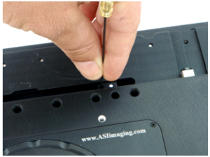 Figure 5b: After loosening the setscrew as shown in figure 2a, move the limit until the “L” appears in the X-axis display as shown in figure 6c. Do not over-tighten.
- Inverted MS2000 stages (for TE-2000 )
-
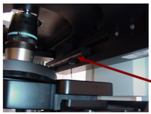 Figure 5b: After loosening the White setscrew as shown in figure 2a, move the limit until the “L” appears in the X-axis display as shown in figure

- MS-8000 stage
-
 Figure 5b. After loosening the setscrew as shown in figure 1a, move the limit until the “L” appears in the X-axis display as shown in figure 5c. Tighten the set screw. Do not over-tighten.
- MS-8000 stage (obsolete old version)
-
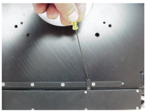 Figure 5b. After loosening the setscrew as shown in figure 2a, move the limit until the “L” appears in the X-axis display as shown in figure 5c. Do not over-tighten.
- Upright MS2000 stage
-
 Figure 5b. After loosening the setscrew as shown in figure 2a, move the limit until the “L” appears in the X-axis display as shown in figure 5c. Do not over-tighten.
- Upright MS-4000 stage
-
Figure 5b. After loosening the setscrew as shown in figure 2a, move the limit until the “L” appears in the X-axis display as shown in figure 5c. Do not over-tighten.
- Upright MS-4400 Stage
-
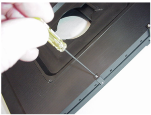 Figure 5b. After loosening the setscrew as shown in figure 2a, move the limit until the “L” appears in the X-axis display as shown in figure 5c. Do not over-tighten.

Setting the X-axis Upper Limit
Please refer to figures 2a & 2b for loosening the setscrews that secure the Y-axis limit switches.
Setting the X-axis Upper
- Inverted MS2000 stages with embedded limits(for Axiovert, Axiovert35 and AxioObserver etc)
-
Figure 6b. After loosening setscrew as shown in figure 2b. Move the sensor until the U appears in the X-axis display as shown in figure 6c.Do not over-tighten.
- Inverted MS2000 stages (for Axiovert 200 HEMQ )
-
 Figure 6b: After loosening setscrew as shown in figure 2b, move the limit until the “U” appears in the X-axis display as shown in figure 7c. Do not over-tighten.
- MS2500 or FlatTop Inverted Stage
-


- Inverted MS2000 stages (for TE-2000 )
-


- MS-8000 stage
-
 Figure 6b. After loosening setscrew as shown in figure 1b, move the limit until the “U” appears in the X-axis display as shown in figure 6c. Tighten the set screw. Do not over-tighten.
- MS-8000 stage (obsolete old version)
-
 Figure 6b. After loosening setscrew as shown in figure 2b, move the limit until the “U” appears in the X-axis display as shown in figure 6c. Do not over-tighten.
- Upright MS2000 stage
-
 Figure 6b. After loosening setscrew as shown in figure 2b, move the limit until the “U” appears in the X-axis display as shown in figure 6c. Do not over-tighten.
- Upright MS-4000 stage
-
Figure 6b. After loosening setscrew as shown in figure 2b, move the limit until the “U” appears in the X-axis display as shown in figure 6c. Do not over-tighten.
- Upright MS-4400 Stage
-


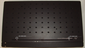
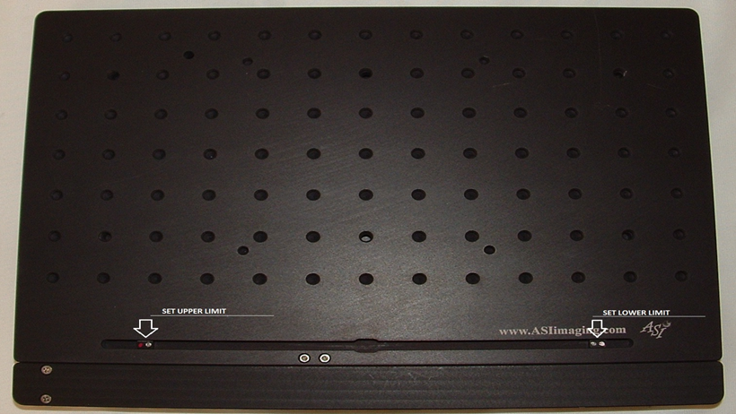
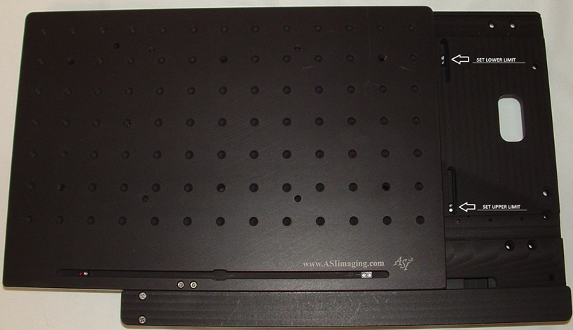
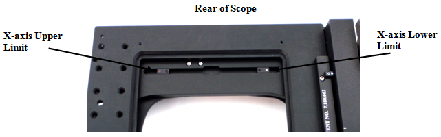
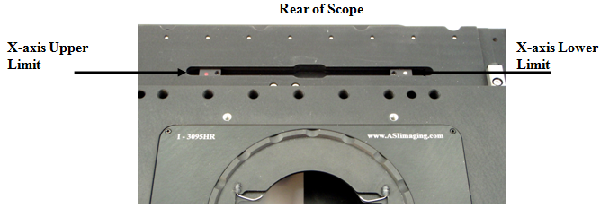
X-axis Range of Travel Limits
The X-axis limits are located on the middle stage plate, towards the rear of the microscope, as shown below in figure 7.
- Inverted MS2000 stages with embedded limits(for Axiovert, Axiovert35 and AxioObserver etc)
-
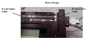 Figure 7

- Inverted MS2000 stages (for Axiovert 200 HEMQ )
-
 Figure 7
- MS2500 or FlatTop Inverted Stage
-
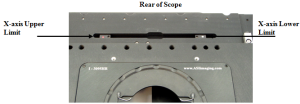 Figure 7
- Inverted MS2000 stages (for TE-2000 )
-
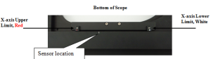 Figure 7
