Table of Contents
Old FW-1000 Control Box Manual
The FW-1000 Control Box has been deprecated, and is no longer available.
The Shutter Control Panel shown in the photo below has been deprecated, and is no longer available.
The current filter wheel hardware options available are the Standalone FW-1000-SA unit and the TGFW card inside the TG-1000 Tiger Controller, see the FW-1000 Filter Wheel Manual.
FW-1000 Control Box
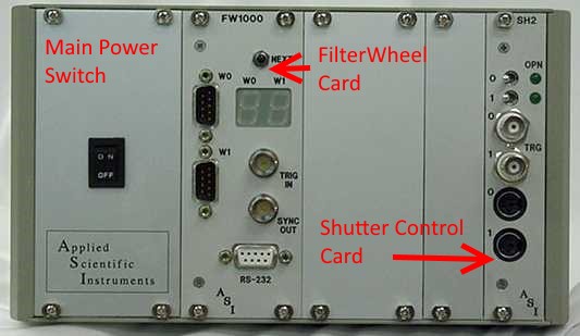
The FW-1000 control box houses multiple control panel cards and allows for more than two wheels as well as future expansion. The Main Power Switch energizes the appropriate internal power supplies to energize the panels inserted into the unit. A FW-1000 system can be supplied with just a Filter Wheel Control Panel, or may have the optional Shutter Control Panel as seen in the photo above. Note: ASI no longer supports mechanical shutters.
One Filter Wheel Control Panel can handle two filter wheels and simultaneously move both wheels to the next set of filter positions. It may be controlled by the button or trigger input on the panel. A Shutter Control Panel can handle two shutters, including the optional built in shutters available with FW-1000 filter wheels. Both filter wheels and shutters may be controlled by computer commands via the RS-232 connector on the Filter Wheel Control Panel. The shutters may also be controlled via the switches or TTL trigger inputs on the Shutter Control panel.
Electrical Characteristics for FW-1000 Control Box
AC Input:  90-264 VAC, 3.3 A (peak), 50/60 Hz
AC In-rush Current (Cold Start):  7 A (maximum), at 240 VAC
Fuse Replacement:
2.0 A Fast Blow 250 VAC, 5x20mm H pack fuse - for 110-120 VAC Operation
1.6 A Fast Blow 250 VAC, 5x20mm H pack fuse - for 210-230 VAC Operation
3.3 A Fast Blow 250 VAC, 5x20mm H pack fuse - for 100-105 VAC Operation
Shutter Control Panel (no longer available)
PLEASE NOTE: ASI no longer supports shutters. The FW-1000 Shutter Control Panel is no longer available.
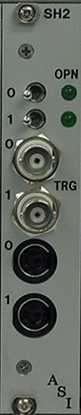
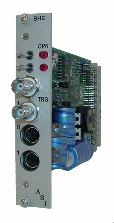
The FW-1000 Shutter Control Panel provides for control for two shutters, 0 and 1. The shutters are connected to the controller with the 0 and 1 6 Pin Mini Din Female Connectors on the front panel. Upon power up, any connected shutter will go to its default position of OPEN or CLOSED depending on the position of the shutter’s toggle switch and the type of shutter (normally open or normally closed). It should be noted that the panel/card will be set for either a normally open or a normally closed shutter at the factory. This setting can be changed using the Shutter Setup command (see page 35). The Shutter Control Panel is controlled internally through the Filter Wheel Control Panel’s RS-232 computer control serial port.
TOGGLE Switches
The two toggle switches for shutter 0 and 1 at the top of the panel allow manual override control of the shutter. When the toggle switch is placed in the left position, the shutter control is in the RS-232 controlled state that defaults to the de-energized position of the shutter at power up. When the toggle switch is moved to the right position, the control panel will energize the shutter for that switch. It should be noted that the switch must be in the LEFT position to be able to control the shutter through the Filter Wheel Control Panel’s RS-232 computer control port.
LEDS
If the shutter has a built in internal position sensor, the corresponding LED will indicate the shutter is in its OPEN position if lit. If no internal position sensor is detected, the LED will always remain unlit.
TRG
A TTL input may be connected to the TRIG IN BNC Connector for external control of each shutter. A +5vdc signal applied to the internal pin of the TRG IN BNC connector (the outer connector is ground) will override any computer controls and energize the shutter.
Order of Precedence
Whether it be computer serial control, toggle switch control, or TRG TTL control of a shutter, an energize signal from any one of them will dominate, and that shutter will remain energized until all control sources return to their de-energized state.
Installation of Cables
FW-1000 Control Box
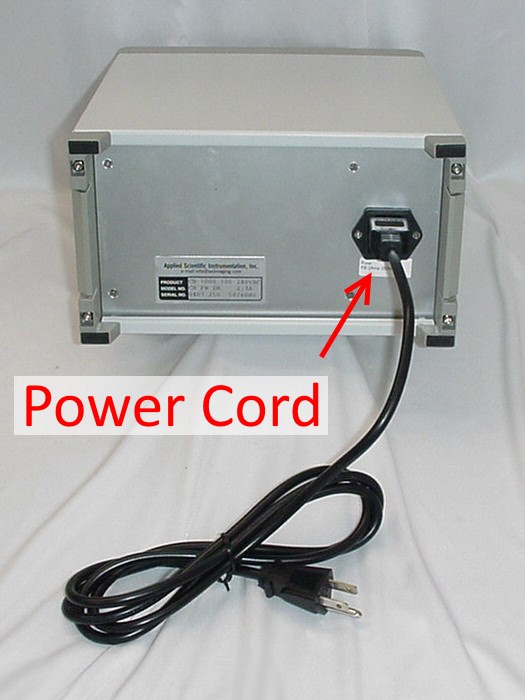
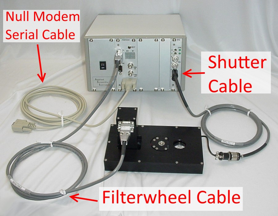
Plug the AC power cord into the rear of the controller. Attach the cable between the filter wheel and the controller. Connect the serial cable between the computer and controller.
Shutter Control Panel Pin-Outs
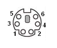
| Shutter Control 0 & 1 Connectors | ||
|---|---|---|
| PIN | SIGNAL | INFORMATION |
| 1 | Shutter + | ~5msec 60vdc peek at start, 5vdc Holding Voltage when energized |
| 2 | Shutter - | Controlled Ground |
| 3 | Position Sensor LED + | +5 vdc |
| 4 | Position Sensor GND | Ground |
| 5 | Position Sensor Return | +5vdc TTL Signal |
| 6 | Position Sensor +5vdc | +5 vdc |
| TRG 0 & 1 BNC Connectors | ||
|---|---|---|
| PIN | SIGNAL | INFORMATION |
| 1 | Energize Shutter | |
| 2 | GND | Ground |
Shutter Specifications
| Methods of Control | Serial Interface |
|---|---|
| TTL Signal | |
| Front Panel | |
| Toggle Switch | |
| Number of Shutter Channels per Card | Two |
| 0%-to-100% Opening Time from Trigger (N.C. shutter) | 8 ms |
| 100%-to-0% Closing Time from Trigger (N.O. shutter) | 7 ms |
| Minimum 50%-to-50% Open Time (N.C. shutter) | 5 ms |
| Minimum 50%-to-50% Closed Time (N.O. shutter) | 13 ms |
| Minimum Total Window 0%-to-0% | 14 ms |
| Minimum Trigger Width | 7 ms |
| Peak Unsustained Repetition Rate | 40 Hz |
| Maximum Sustained Repetition Rate | 5 Hz |
Jumper Settings for Shutter
On filter wheel jumper JP4, connect 1-2 and 3-4.
On the shutter card jumper J1, connect 1-2, 3-4, and 5-6.
Deprecated Serial Commands
The following commands are used to control shutters with an SH 2 controller in the same cabinet as the FW-1000 controller. The parameter n may have any value from zero to (2N 1), where N is the number of shutter controller cards in use.
Shutter Open
Syntax: SO n
Opens shutter number n.
Shutter Close
Syntax: SC n
Closes shutter number n.
Shutter Query
Syntax: SQ [n]
Returns a decimal status byte from a shutter control register. The n parameter is optional in the Shutter Query command. If no n is specified, then the command returns the status byte from the most recently used shutter controller. If no shutter commands have been issued since the last system startup, then the command returns the status byte from the controller of shutters 0 and 1. If no SH 2 Card is present, 0 is returned.
In the descriptions of Bit 0 and Bit 1 below, an energized, normally open shutter is closed; a de-energized, normally open shutter is open; an energized, normally closed shutter is open; and a de-energized normally closed shutter is closed. In other words, a de-energized shutter is always in its normal state. The binary equivalent can be decoded as follows:
| Bit 0 | 1 = Shutter 0 is de-energized |
|---|---|
| 0 = Shutter 0 is energized | |
| Bit 1 | 1 = Shutter 1 is de-energized |
| 0 = Shutter 1 is energized | |
| Bit 2 | 1 = Shutter 0 is closed or has no sensor |
| 0 = Shutter 0 is open and has a sensor | |
| Bit 3 | 1 = Shutter 1 is closed or has no sensor |
| 0 = Shutter 1 is open and has a sensor | |
| Bit 4 | SH2 Card is present |
Shutter Setup
Syntax: SS x
Supports shutter control. Normally, the SC command causes the controller to energize a shutter, and SO causes the controller to de energize it. Most shutters are normally open; i.e., open, unless energized by the controller via the SC command. The SS parameter x is a binary number representing eight bit positions, i.e., an integer in the range 0…255. Within x, if some bitk is set, then shutter k is normally closed. With this setting in effect, the effects of SO and SC are reversed. Instead of SC causing the controller to energize the shutter, SO energizes it, and vice-versa. Once determined, this value may be saved to non-volatile (flash) memory using the RS command.
The default value of x is zero, denoting that all shutters are normally open.
Examples: SS 2 is correct if Shutter 1 is normally closed, because x has Bit 1 set. SS 3 is correct if shutters 0 and 1 are normally closed, because x has Bits 0 and 1 set.
Cleaning & Maintenance
Cleaning should be done with a 70% isopropyl alcohol solution. Maintenance should only be done by ASI, or an ASI approved technician - no user serviceable parts inside.
If the equipment is used in a manner not specified by the manufacturer, the protection provided by the equipment may be impaired.
Warranty
Applied Scientific Instrumentation, Inc., hereafter referred to as ASI, guarantees its equipment against all defects in materials and workmanship to the original purchaser for a period of one (1) year from the date of shipment. ASI's responsibility to this warranty shall not arise until the buyer returns the defective product, freight prepaid, to ASI's facility. After the product is returned, ASI at its option, will replace or repair free of charge any defective component or device that it has manufactured. The warranty set forth above does not extend to damaged equipment resulting from alteration, misuse, negligence, abuse or as outlined below:
1. Equipment not manufactured by ASI that is offered as part of complete systems carry the original equipment manufacturer's warranty.
THE WARRANTY AND REMEDIES SET FORTH ABOVE ARE IN LIEU OF ALL OTHER WARRANTIES. APPLIED SCIENTIFIC INSTRUMENTATION, INC. EXPRESSLY DISCLAIMS ALL OTHER WARRANTIES WHETHER EXPRESSED, IMPLIED OR STATUTORY, INCLUDING THE WARRANTIES OF MERCHANTABILITY AND FITNESS FOR A PARTICULAR PURPOSE AND AGAINST INFRINGEMENT.
In no event will ASI be liable for incidental or consequential damages, even if ASI has been advised of the possibility of such damages howsoever, arising out of the sale or use of the products described herein.