Table of Contents
ASI CRISP Control
For general information about CRISP, please visit the manual.
Setup
The plugin comes with Micro-Manager 2.0 by default, it also comes with Micro-Manager 1.4 but is not actively developed.
First, make sure that you add CRISP to your hardware configuration. You can access the Hardware Configuration Wizard through the Devices drop down menu. If you need further guidance, check out the Hardware Configuration Guide.
You can get the latest version of the plugin by installing the latest nightly build of Micro-Manager 2.0.
Accessing the plugin
You can find the plugin in the Plugins > Device Control > ASI CRISP Control
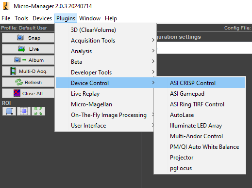
Accessing the plugin window
Micro-Manager Main Window > Plugins > Device Control > ASI CRISP Control
Plugin Controls Explained
The text above the spin boxes contains the axis CRISP controls, in the image below it's Z.
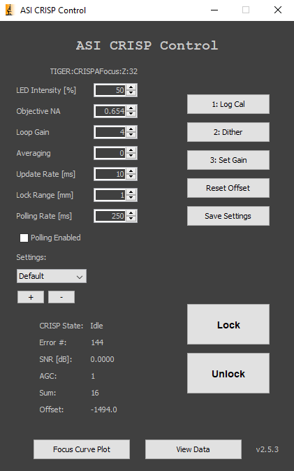
The plugin interface
This is the Micro-Manager 2.0 version.
Buttons
- 1: Log Cal: puts the CRISP in Log Amp Calibration state and measures SNR
- 2: Dither: causes CRISP to dither in order to measure the Error #
- 3: Set Gain: puts the CRISP in Set Gain state
- Reset Offset: resets the focus offset to zero for the current position
- Save Settings: saves the settings to the controller (all spinners except polling rate)
- Lock: sets the focus position
- Unlock: unlocks the focus position
Spin Boxes
- LED Intensity [%]: controls CRISP’s infrared (IR) LED from 0-100%
- Objective NA: the objective’s numerical aperture
- Loop Gain: controls the gain multiplier or loop gain; decrease the value if CRISP seems to oscillate or jitter
- Averaging: the number of samples to be averaged
- Update Rate [ms]: the update rate in milliseconds
- Lock Range [mm]: limit the lock range in millimeters
- Polling Rate [ms]: the rate that the status is updated in milliseconds
Check Box
- Polling Enabled: directs the Plugin to poll or query the controller at frequent intervals for CRISP state, error number, and SNR; uncheck when done with the 4-step calibration
Settings
- Combo Box: the current software settings profile
- Button +: add a new software settings profile to the the list
- Button -: remove the last software settings profile from the list
Status
- CRISP State: such as Idle, Calibrating, Ready, In Focus, etc.
- Error #: during DITHER higher error values are better; after SET GAIN the Error # will be close to zero
- SNR [dB]: should be at least 2 dB or else CRISP performance may be unstable and lock will be lost easily; increasing LED intensity and performing the 4-step calibration again to increase the SNR
- AGC: minimum of ~20 is acceptable for average samples; may be much higher for very reflective samples
- Sum: indicates the amount of light hitting the photodiode; if outside 50-80, redo the 4-step calibration
- Offset: the difference between the locked-in focal position and the current position
Buttons
- Focus Curve Plot: run the focus curve routine and plot the results.
- View Data: load and view focus curve data plots.
Quick Setup Guide
- Enter the objective’s NA (which affects the dither).
- Start the 3-step calibration1) by clicking the 1: Log Cal button.
- Check the SNR display. If < 2 dB, click through the rest of the 3-step calibration, increase the LED Intensity, and begin the calibration again. If SNR is still low after the LED is at maximum intensity, proceed to the next step anyway.
- Click the 2: Dither Button.
- Check the Error #. It must be at least +/- 100; if it isn’t, move the Lateral Adjustment Screw. The farther from zero the error number, the stronger the lock.
- Press the 3: Set Gain button.
- Press the Lock button to preserve the focal position. (Press the Unlock button to release CRISP's focus lock.)
- If CRISP loses lock, repeat the calibration steps and try to get a higher error number after dithering.

Lateral Adjustment Knob
Used to increase error number during dither
Additional Tips
If you would like CRISP to maintain focus at a certain position, but the error isn’t 0, use the Reset Offset button to make your desired focal position have “0” error.
Further Reading Refer to CRISP: Continuous Autofocus System for a description of CRISP operation and troubleshooting guides.