Table of Contents
Video Auto-Focus Card: Standalone Operation Manual
Introduction
The ASI auto-focus system is an electronic circuit that detects the high spatial frequency information present in a video signal coming from an analog camera, and converts it to a focus signal for each frame – the better the focus, the larger the focus signal. The focus signal has amplitude between 0 to 5 Volts. An onboard ADC is provided; lets the user read the focus signal as an 12bit binary number with an I2C interface. Depending on the sample and the type and power of the objective, the conditions to achieve the best focus signal may change. To compensate, the system incorporates a set of I2C controlled digital potentiometers that lets the user calibrate various internal parameters to get a good focus signal. The system also allows user to highlight any subset of the video field and generate focus signal for it.
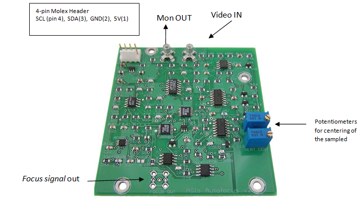
Card IOs
- Power Requirement: Regulated 5 Volts with at least 50mA current.
- Video IN: Monochrome or Color, NTSC or PAL video
- Mon OUT: Video Monitor, Output which shows a highlighted/sampled video for which focus signal is generated.
- I2C: SDA, SCL
- Focus signal: 0 to 5V, max output current 50mA
- ADC: ADS1000 converts the Focus signal to a 12bit Binary Number that can be read with I2C. Onboard I2C address
0x90 (1001000x)
| Table 1: Molex Header pin out | |
|---|---|
| 4-Pin Molex | Header pin out |
| 1 | 5V |
| 2 | GND |
| 3 | SDA |
| 4 | SCL |
Card Controls
- Two mechanical trim pots adjust centering of the sampled video region vertically and horizontally.
- Dual I2C controlled digital pots control the width of the actively sampled region vertically and horizontally. On board I2C address
0x58 (0101100x). - Dual I2C controlled digital pots control the circuit gain at two locations in the signal chain to allow for large dynamically variable visual scenes. On board I2C address
0x5A (0101110x).
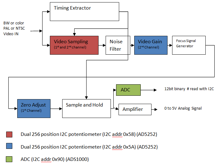
Brief Description of Card’s Working
- The card runs at 5V and needs a minimum current of 50mA.
- When a video signal is applied to the card a timing circuit extracts various timing information. This lets the card be used with 60Hz NTSC video, 50Hz PAL video. ASI has so far only tested the card with NTSC and PAL video, upon request we can test the card and modify it for other analog video too.
- Various I2C chips lets the user set the cards internal settings like subset of video to be processed , gains and zero adjusts of internal circuitry and also to read the focus signal .
- After the timing information is extracted the video is passed to a cropping circuit. Using a dual I2C controlled digital potentiometer (I2C address 0x58) the user can select the width of video signal to be sampled. Additional details are furnished in section 3.1.
- After noise filtering the video signal is sent to the circuit that detects and sums the high spatial frequency information in a video signal to generate the focus signal. A sample and Hold circuit only updates the output amplifier at the end of each frame.
- Here again the user is given control of another dual digital potentiometer (I2C address 0x5A). The second potentiometer is used to control the amplitude of the video signal supplied to the frequency to amplitude converter circuit. The first potentiometer helps with the zero adjust. The role of these potentiometers is elaborated in the calibration section 3.2.
- And finally the user can either read the focus signal amplitude directly, or use the onboard 12bit ADC to read the value digitally through I2C interface.
I2C Controls
Video Sampling
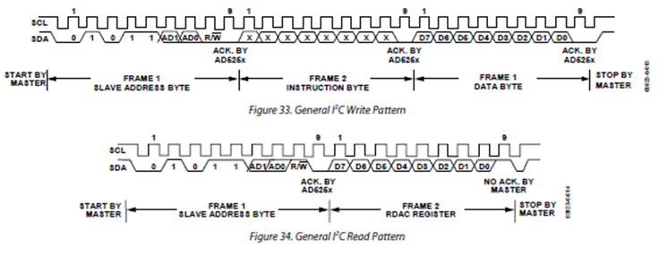
Video Sampling option is available to users to define a subset video and generate focus signal for only that video field. This feature is useful in avoiding false focusing when a video has multiple objects or noisy background. Selection of subset video is done by changing resistances with AD5252 IC; it’s a dual channel, digitally controlled potentiometer with 256 positions, with nonvolatile memory and an I2C interface. The datasheet of this IC can be found here. The address of this IC on the board is 0x58 (0101100x)
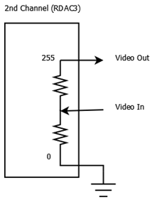
Each channel controls the resistance and thus controls the width of the actively sampled region vertically and horizontally. Each channel has an 8bit register (0x00 to 0xFF) RDAC1 (internal chip address 1) and RDAC3 (internal chip address 3) that carries setting for each channel/potentiometer. When both the channels are set to 0xFF, then the entire video is sampled, and when the channels are set to 0x00, then the entire video is ignored. Since the IC are nonvolatile, once the values are picked they can be saved into the non volatile memory, which are restored to the RDAC registers at system power-on.
Please refer to the AD5252’s manual for details on communication with the IC.
Connecting a monitor to the Monitor out of the autofocus card shows the sampled video as a highlighted rectangle. Two mechanical trim potentiometers are provided to let the user centering the sampled video.

Calibration
The second dual potentiometer is also an AD5252. The address of this IC on the board is 0x5A (0101110x). This IC controls some of the circuitry that detects and converts the high spatial frequency signal in a video to a focus signal. The first channel/potentiometer is a zero adjusts and the second channel controls the amplitude of the video signal applied to the circuitry.
Settings Zero Adjust
The first channel of the second potentiometer is the zeroing potentiometer. When a blank video signal (completely white or black) is applied the focus signal generated must be zero volts. But due to internal offsets this value is not zero, the zero potentiometer is adjusted so that a blank video signal results in zero focus signal. To set the potentiometer, first video signal to the focus signal circuitry must be cut off. This can be done with the second channel of the potentiometer. By writing to the RDAC3 register a value of zero, video signals amplitude is reduced to zero. Now set the RDAC1 register i.e. first channel such that focus signal is zero.
Video Gain
The second channel/potentiometer controls the amplitude of the video signal applied to the focus signal extractor circuitry. During normal operation RDAC3 register is written with 0xFF, to let all the video signal pass, but during calibration this channel is set to 0x00, to help in setup of zero adjust potentiometer of channel one.
ADC
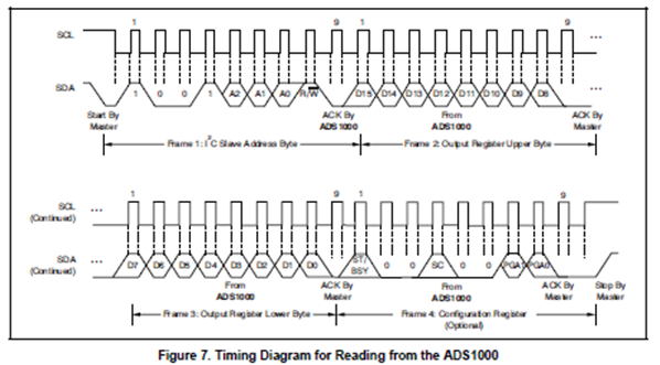
The User can read focus signal by connecting a coaxial cable to the Autofocus card. Or can read digitally through I2C. Analog to Digital Converter ADS1000 IC is provided on the card, it is a 12bit ADC(12th bit is sign bit, so only 11bit 0 to 2047) it has an I2C interface and runs at 128 samples per second. Please refer to the ICs datasheet on further details on how to communicate with the IC. Address of this IC on the board is 0x90 (1001000x)
ASI’s Focusing Routines

This is the focusing routine ASI uses with the autofocus card and its MS2000 Microscope Z stage controller. When the controller is given an auto-focus command, it moves from a starting position to a stop position, constantly checking the focus signal. The focus signal goes through a filtering/averaging process to remove unwanted false focuses caused by noise and other disturbances. The controller takes the filtered signal and watches for focus signal to increase in value. When a new maximum value is detected, the controller keeps track of the position where it was found. When the end of the scan is reached, the controller goes back to the position that had the highest focus signal.
A slight improvement of this routine is “Hill Detect“ routine. In this routine, the auto-focus controller watches for the focus signal to increase in value and then when it starts to decrease, a hill is detected. At this point, the auto-focus controller stops the scan and goes back to the position that had the highest focus value found on the hill. This is somewhat subject to false focusing and should be used only on high contrast single-layer samples.
Testing the Autofocus Card
Before shipping, ASI uses a series of test video patterns to test and calibrate the cards.
ASI uses a computer with NTSC video out graphic card to apply these test patterns to the autofocus card.
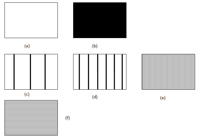
- Patterns a and b are referred as blank video patterns and should result in zero focus signal. They are the patterns ASI applies to the card during factory calibration.
- For test pattern c, d and e the focus signal should progressively increase.
- Test pattern f demonstrates the limitation of the autofocus card. Because of design, the ASI’s autofocus card process the video line by line, so when pattern f is applied, the card does not notice any contrast or edges and results in a zero focus signal. However in real world there are very few objects or specimens with perfect horizontal pattern like f. Even a slight skew is enough for the card to extract some focus signal.
- As the card only process the spatial frequency signal and ignores the color information. Color video patterns should give similar results.
Troubleshooting and Optimization
Focus Signal is fluctuating a lot
Focus signal depends a lot on the quality of video input. A fast moving or noisy video can result in fast fluctuating focus signal. Try running the signal through a low pass filter, or an averaging algorithm if read digitally.
An unfocused spot is giving higher focus signal then a focused spot
Here are a few things you can try when the focus signal reads a higher value at a defocused spot than at a focused spot:
- Turn off any Automatic Gain Control (AGC) settings on your video system and use a Manual or Fixed Gain setting instead.
- The illumination might be insufficient; increase the lighting on your sample.
- Limiting the background might help; decrease the width of the actively sampled video as described in Video Sampling section
Focus signal ramps up and saturates (5Volts for analog signal, 2047 if read digitally through ADC)when the sample is motionless and the focus controller is quiescent.
This problem occurs when the Zero Potentiometer (First channel of 2nd potentiometer) is incorrectly set. This can be corrected by calibrating the potentiometer again as described in Settings Zero Adjust section
Focus signal is saturating (5Volts for analog signal, 2047 if read digitally through ADC)
Try reducing the width of actively sampled video as described in section Video Sampling section. Or try reducing the amount of video signal applied to focus signal generator circuitry as described in Video Gain section